SPICE is a very useful tool when used correctly and is used far beyond its original purpose — “Simulation Program with Integrated Circuit Emphasis.” It is now used for simulation of many non-integrated circuits. However, whichever type of circuit you use it for, you need to be aware of its limitations.
The modeling has been changed significantly over the years, as anyone who remembers the original basic MOSFET models will know. The newer models help to better model the smaller geometry devices in integrated circuits as the years progress. Of course, those simulator models are only useful if they match your actual devices. At a more fundamental level, when should you use the different types of simulation and does it matter which you use?
The main simulation types are transient, AC, DC, and noise. Additionally, there are transfer function, operating point and distortion analyses. One common misunderstanding is what the AC analysis does exactly so misinterpreting the results is a risk. An AC analysis is a small signal analysis which analyses the response to a very small input signal. That could be the same as the response to a large signal, but not necessarily. Take the following simple example.
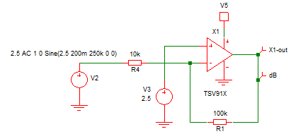
The gain should be 20dB. An AC analysis confirms that for low frequencies. At 200kHz the gain has dropped slightly to 19.92dB in the AC analysis because the gain bandwidth of the opamp is only 8MHz. A transient analysis with 0.4V peak-peak input results in 3.94V peak to peak out, compared to 3.96V which would be expected from the AC analysis. So, pretty close.
Here’s another example:
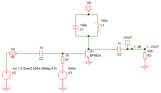
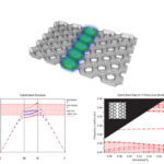
This is not a “design” but a simple circuit to illustrate the problem. It is a tuned class C amplifier at around 50MHz. Conduct an AC analysis, and you will get the following:
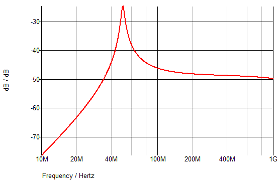
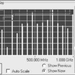
The peak gain is -25dB, so not much of an amplifier. Note that the transistor is biased, so it is turned off with 0.5V on the base. However, conduct a transient analysis with a 1V peak-peak 50MHz sine wave and you will get the following output:
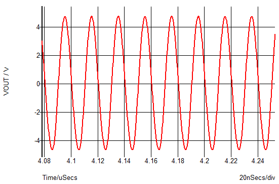
So, a peak-peak output of 9.4V – a gain of 19.5dB. The difference between the two simulations is the difference between small signal analysis and large signal analysis. The small signal (AC) analysis doesn’t show how the circuit will be used realistically ( i.e., with a large signal). You could duplicate the AC analysis results with the transient analysis but not the other way round.
If you change the input signal in the transient analysis to 1mV peak-peak rather than 1V, you will see only 57µV of peak-peak output signal. So the “gain” is -25dB or the same as the AC analysis. The reason the results are now the same is that by keeping the input signal very small, we are not altering the biasing of the transistor.
Unfortunately, there is no AC analysis for large signals (although there are tools specific to RF design more suited to such design problems) so you must use a transient analysis. It is not only RF design which will result in large signal problems. An audio amplifier or any circuit working with large signals could have similar problems depending on the design.
So, what of the other types of analysis? DC analysis is purely related to DC signals. You sweep a DC voltage (or a device parameter) and see how it affects the DC voltages in your circuit. A simple example would be the biasing of a transistor.
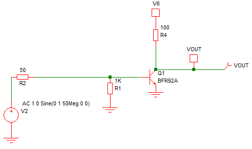
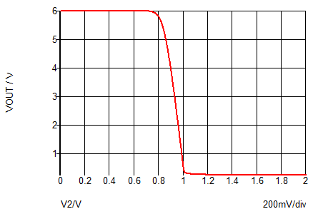
If you sweep the input voltage V2, you will see the output voltage stay at 6V until the transistor starts to turn on when it will then rapidly drop to the saturation voltage. You can see that when V2 is around 0.93V the output voltage is at the mid rail point of 3V.
A DC analysis can be useful in trying to work out why a circuit isn’t working as expected, particularly where the problem is the biasing. For example, if you have an amplifier design but it has no gain and/or the output is stuck at 0V or Vcc, a DC analysis could help to track down the error in your design/biasing. Another option is to sweep a resistor value with a fixed voltage. In addition to analyzing biasing, this option could be used to simulate the response of a circuit with a thermistor.
The noise analysis is usually treated as an extension of the AC analysis. It sums all the noise sources in a circuit (resistors and active devices) taking into account where they are in the circuit and the relevant gain (small signal transfer function) at the point at where the noise is injected. A resistor on the output of an amplifier will usually have a lot less effect on the total output noise than a resistor on the input. Some resistors will not contribute to the output noise if their effect is decoupled with a capacitor, for example. In fact, noise analysis is quite a subject in itself so … to be continued.


Leave a Reply
You must be logged in to post a comment.