(editor’s note: Intrigued by the problem? Have a question or another solution? Then click the “Read more” link and follow the conversation on EDAboard.com or log in to EDAboard and participate in the analog forum threads.)
What kind of noise in a resistor and double poly cap? – I know there is a thermal noise in a resistor but are there any other noise type in a resistor? Besides the resistor, what kind of noise is there in a double poly cap or MIM cap? Read more
How would temperature affect current flow in a resistor? – Would temp increase current flow in a resistor? Some say for a conductor, increasing temp will increase resistance and for an insulator, increasing temp will decrease resistance. So, a resistor is more of an insulator, right? Read more
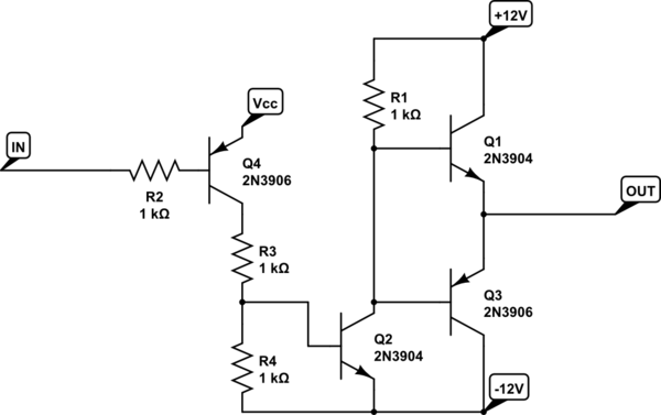
Convert 1 MHz square wave PWM (5v and GND) to 1 MHz square wave (+20v and -20v) – I’m planning to convert 1 MHz PWM from a microcontroller (5v and GND) to a positive and negative (+20v and -20v) PWM (1 MHz). I already did this by using a BJT transistor (BD139 and BD140). The circuit works to convert the (+5v/GND) PWM to (+20v/-20v) PWM with 100 kHz frequency. But when I raised the frequency to 1 MHz, the output was gone missing (drop to 0 V). Could anyone help me to get the solution of my problem? Read more
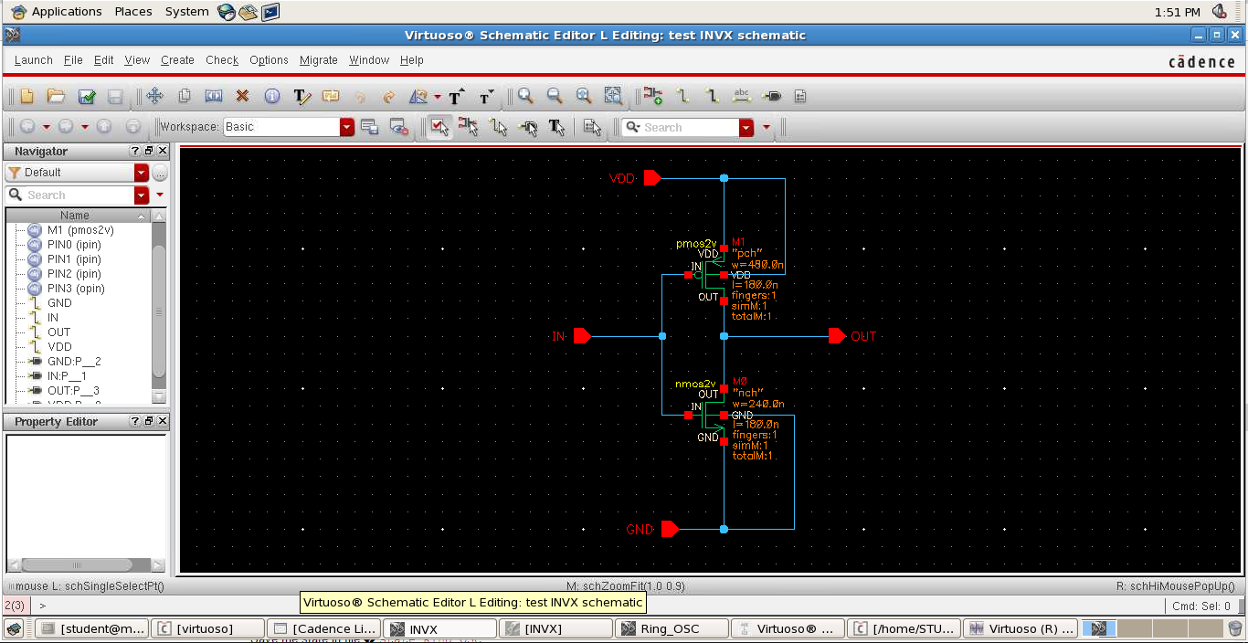
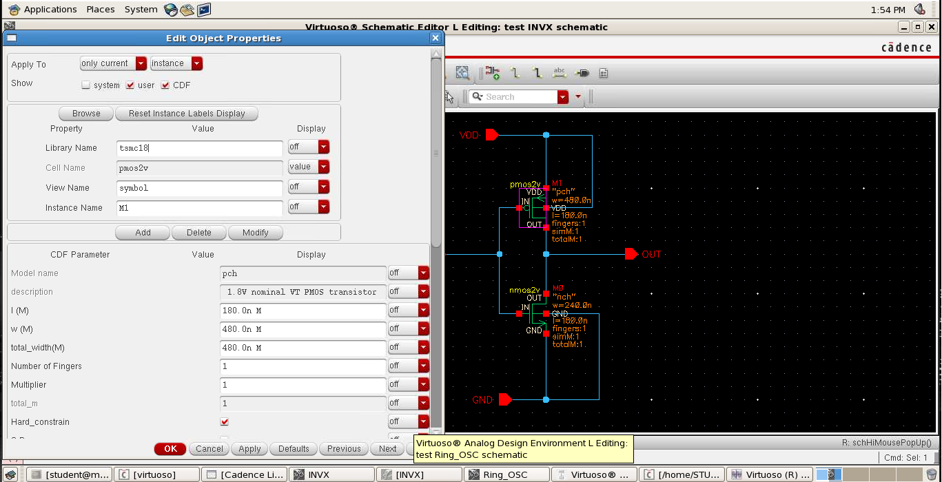
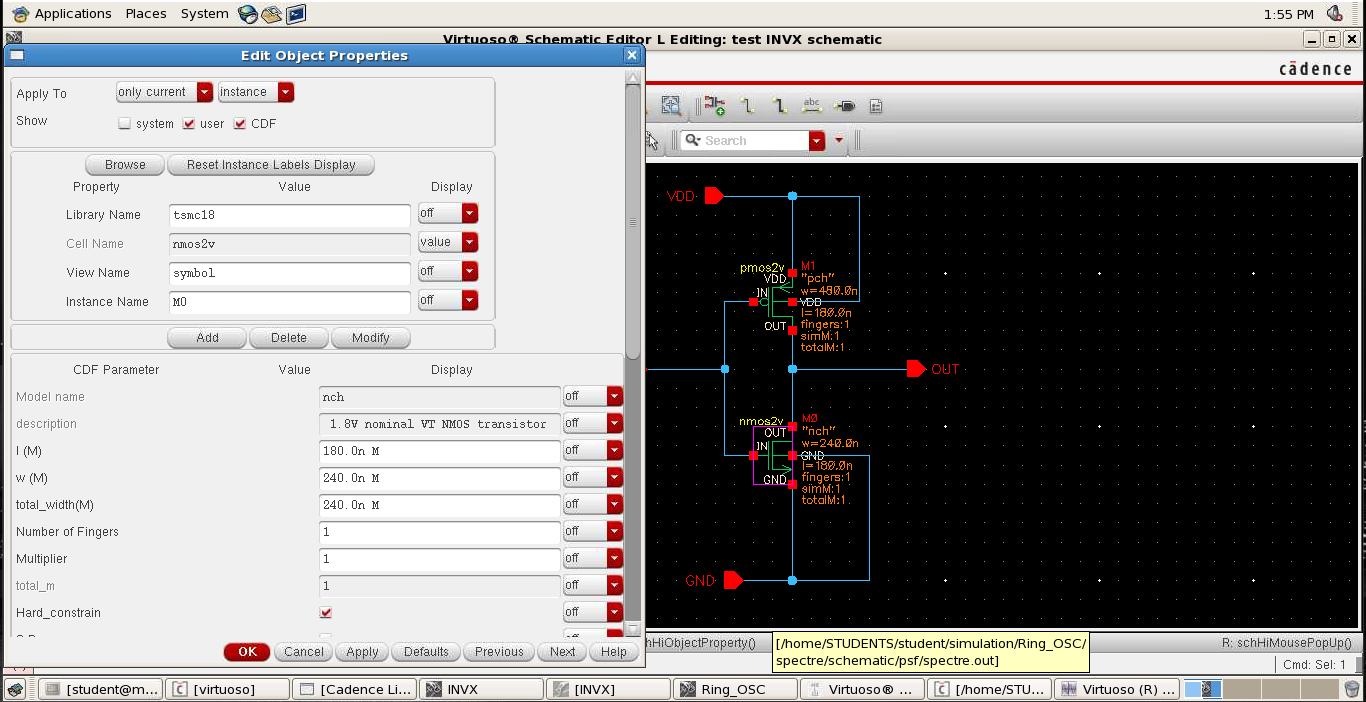
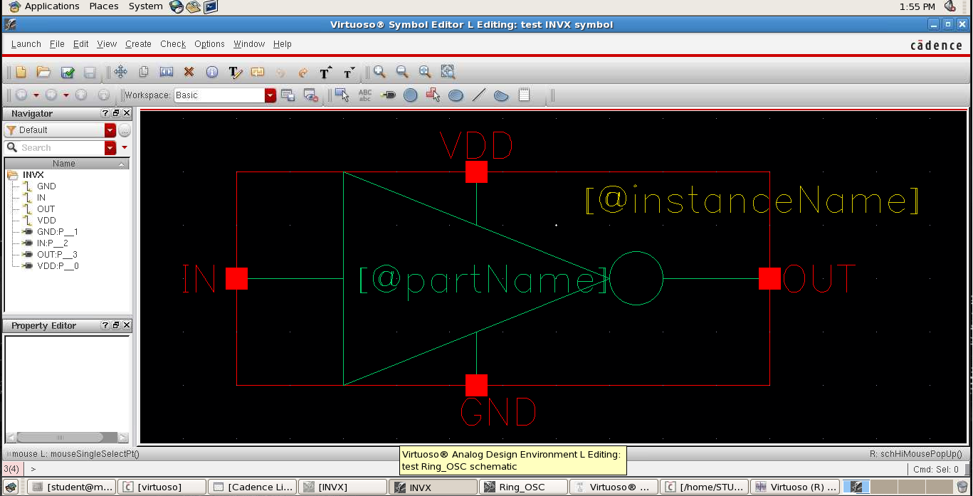
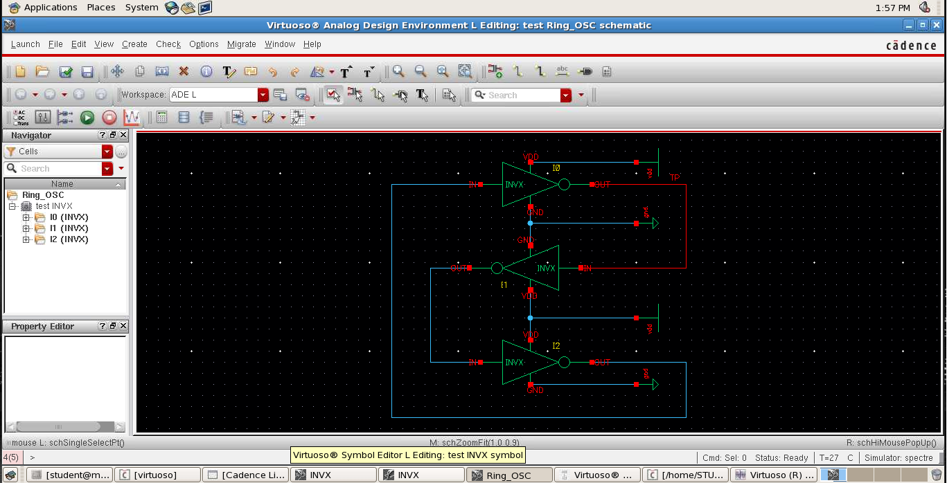
How do I simulate a 3-stage ring oscillator? – I made the schematic for the inverter, then I setup the symbol for it and using that symbol I’ve quickly put together a 3-stage ring oscillator. I need a transient analysis for the simulation of the circuit, a PSS analysis to determine the frequency of oscillation and a PNOISE analysis to determine the phase noise of the designed ring oscillator. Can someone please explain how do I approach all of these? Read more
Driving MOSFET for current-measuring application – A uC’s PWM output will control 2A to 6A current through a heating wire and since the resistance might change, the current value roughly will be fed back to ADC of the uC for regulation etc. The circuit will be soldered on a perf board. I decided to use a single-supply op amp and low-side sensing to avoid common-mode-voltage related issues. The freq. of the uC PWM is 500Hz and the PWM pulses are 0/5V. Here is the datasheet of the MOSFET and here is how I’m planning to wire it:
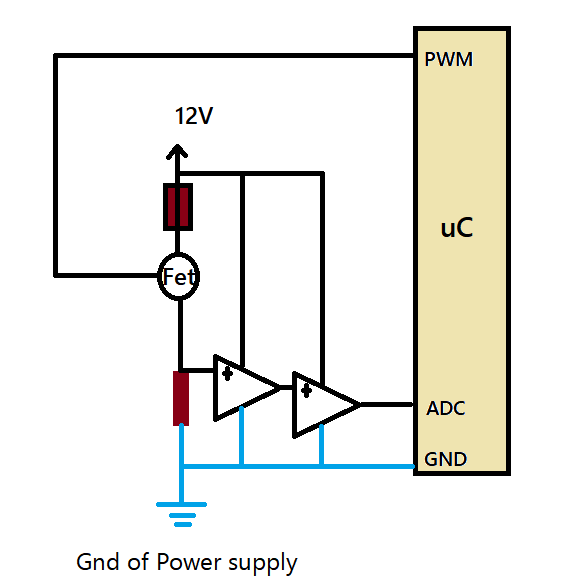
And here is the power dissipation of the MOSFET at 95% PWM (you can see the peak and average power):
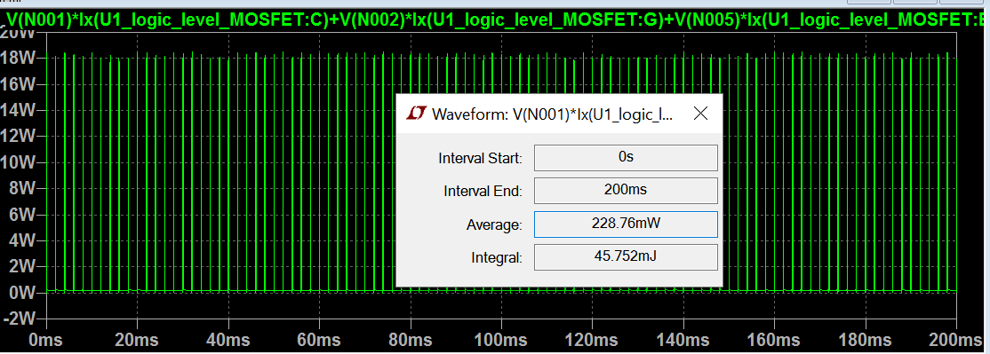
My questions are: Do I need to worry about a driver for the MOSFET? Do I need a heat sink? Is 50mΩ resistor good for this application? And what type of capacitors should I use for the active filter’s 1uF caps? Read more
PTC overcurrent protection – I am working on a transimpedance amplifier current to voltage conversion where the input current is 25 mA(max). I want to add some protection on the input side. Should I use Littelfuse PTC resettable fuses? If accidentally, the terminals are applied to 230V AC, the fuse should protect the circuit. I have selected the Littelfuse part no: 250S130DR. Is that right? Read more
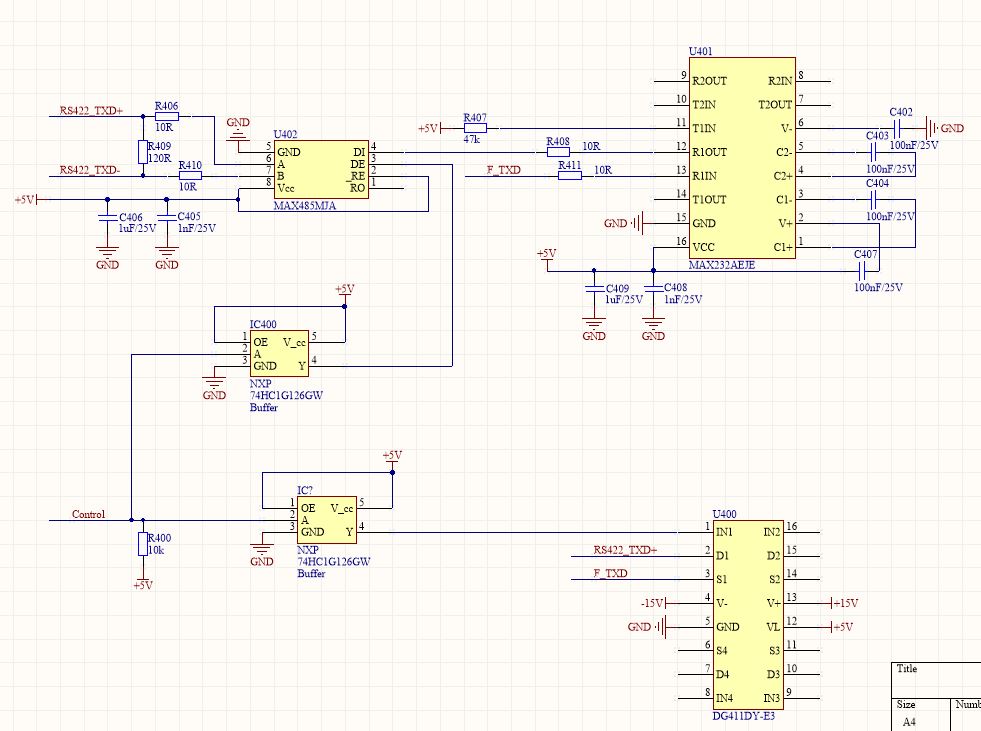
Comments on this circuit – I designed a circuit, which can share RS422 and RS232 on the same pin. When “Control” is high, which has been pulled up to +5V. IC400 Y =High, then U402 works properly, and U401 pin 13 F_TXD (i.e. RS232 TXD signal is converted to RS422 signals by U402). At the same time, U400 IN1 is “High”, i.e. D1/S1 is OFF. So RS422_TXD+ pin is the TXD+ of RS422. When “Control” is low, which should be linked to GND by GPIO, then U402 A/B are in high impedance, at the same time, U402 _RE is high, then U402 isn’t in “receiver” status either. But U400 D1/S1 is ON. So RS422_TXD+ pin is the TXD pin of RS232. Finally, share the same pin for RS422 and RS232 signals? Read more
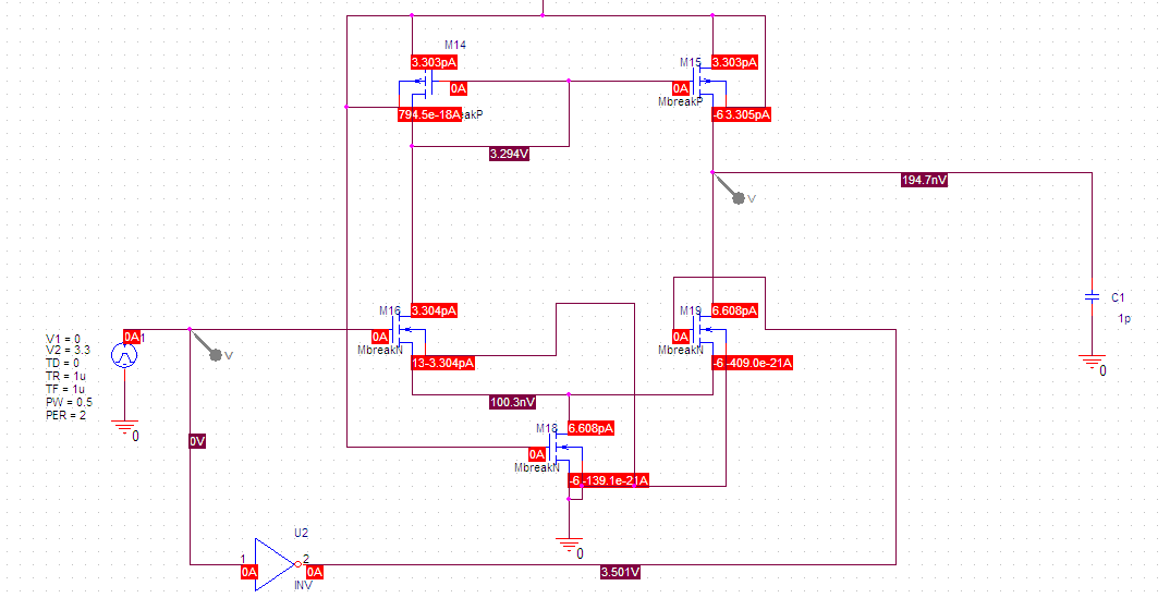
There is not enough current running in my amplifier simulation – The M19 gate is at 3.5V and the transistor is on. Why is it only drawing 6.6pA? Also. it doesn’t add up. M19 drain current is not equal drain current of M15. Read more
TV transmitter connection with antenna – I am making this transmitter and I want to test it by attaching it by wire to a TV antenna output that has two terminals – inner and outer. How do I connect it? The outer terminal is the GND? Read more
![]()
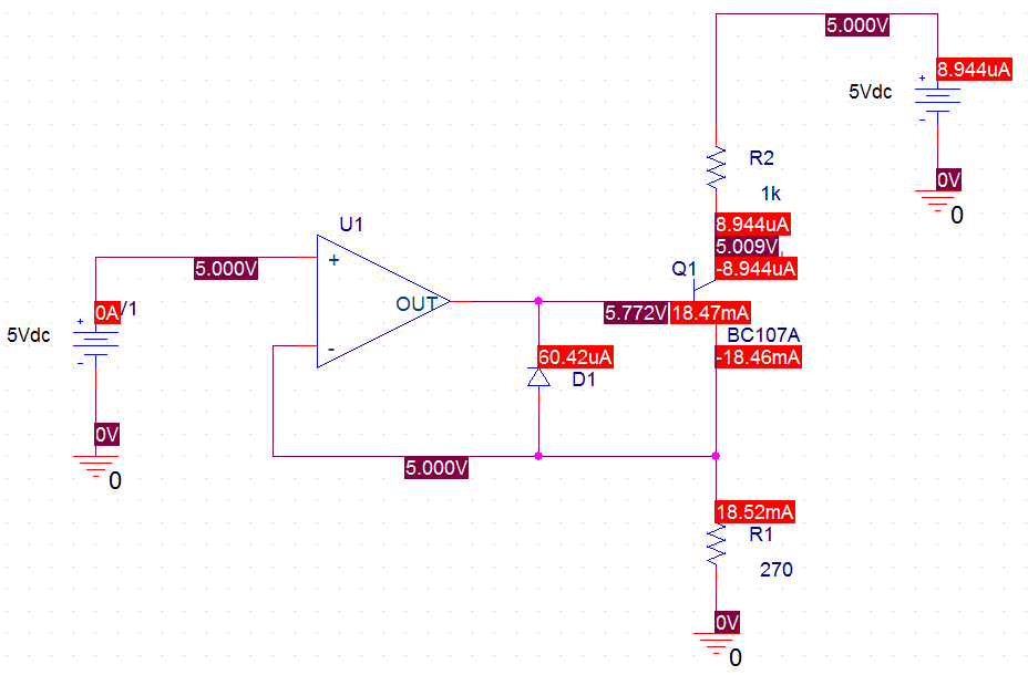
Converter supply/input help – I have this problem where I need to propose the supply/input voltage and the output current (that I want to obtain) and then to calculate and choose the correct components so my circuit can work.
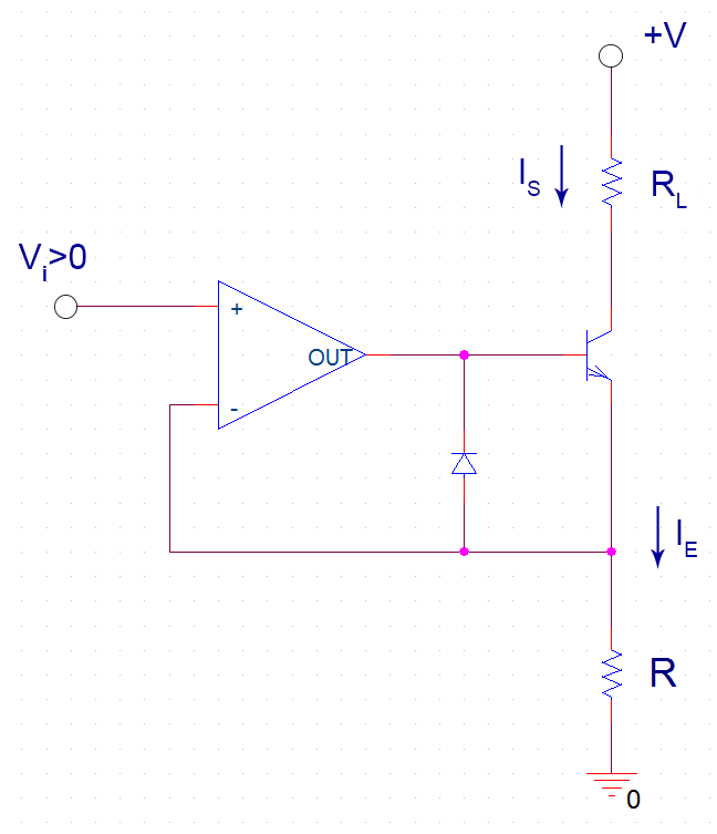
So, I choose the supply to 5V and the output that I want to obtain to 20mA. From my calculations, I got R = 250, and i choose it 270Ω (standard). But now, my teacher wants to calculate the values for the NPN transistor and choose one properly (I choosed BC107a, but I don’t think it’s good, because I didn’t make any calculations). I also tried to do my best with the schematic in Orcad. Read more

Leave a Reply
You must be logged in to post a comment.