By Peter Matthews, Senior Technical Marketing Manager, Knowles Precision Devices
Get a handle on the differences between working at the traditional sub-6 GHz frequencies and mmWave frequencies. The old design techniques won’t work in this new world.
Turning 5G wireless communication into a widespread reality will require the use of mmWave frequencies. But if you have spent much of your career working in the sub-6 GHz range, there are several critical differences you need to know about up front about mmWave signals. This article highlights three key things you need to consider before working with 5G mmWave signals. They include:
- An overview of how the rules and specifications are different for mmWave,
- The different key RF design challenges to consider, and</li
- The different filtering technologies available for these higher frequencies.
Different rules
While mmWave frequencies can push data rates to new levels, they suffer from attenuation and thus have a short range. When shifting from LTE, or even 5G applications operating between 4.1 GHz to 7.125 GHz (or what is known as FR1), to operating at higher frequencies between 24.25 GHz to 52.6 GHz (FR2), there are different “rules” or performance requirements you need to understand. You can go straight to the source and look at the 3GPP Specification 3GPP TS 38.104 V17.2.0 (2021-06).
This specification defines performance requirements for 5G New Radio (5G NR) access network technology. Beyond defining the FR1 and FR2 frequency ranges where 5G can operate, this specification also highlights a variety of additional performance requirements that you should understand when building mmWave base stations and small cells. This includes important criteria such as base station classes, differences in channel bandwidths, and how to test for and handle unwanted emissions.
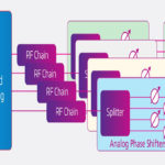
For example, because 5G uses multiple antennas for beam steering, it is no longer practical to use traditional methods for RF testing. Instead, over-the-air testing is now the preferred method, which means specifications for these new tests needed to be defined. This specification also defines how to handle operating band unwanted emissions (OBUE). This is important to consider for 5G, as OBUEs are strongly tied to the operating bands in question. There are two sets of requirements for FR2 depending on frequency. Additionally, FR1 uses multiple configurations where you can measure emissions in different parts of the system (type 1-C, 1-H, and 1-0). In FR2, there is only one configuration (type 2-0) and you must perform these measurement over the air.
The performance requirements defined by the 3GPP Specification are then used by standards bodies such as the Alliance for Telecommunications Industry Solutions (ATIS) in the United States and the European Telecommunications Standards Institute (ETSI) in Europe to create applicable standards to which equipment providers must adhere.
Different RF design challenges
As frequency increases, wavelength decreases. That poses a challenge because in traditional arrays, an inter-element spacing of less than half the wavelength (λ/2) is required to mitigate grating lobes. A 28 GHz band antenna, for example, needs approximately 5 mm of inter-element spacing. As a result, systems must be much more compact. Some of the technologies that work at 4G frequencies will not work at FR2. To better illustrate the shift in system design required for higher frequencies, Figure 1 shows the physical scale of different wavelengths compared to some familiar references, starting at 700 MHz and moving up to 39 GHz.
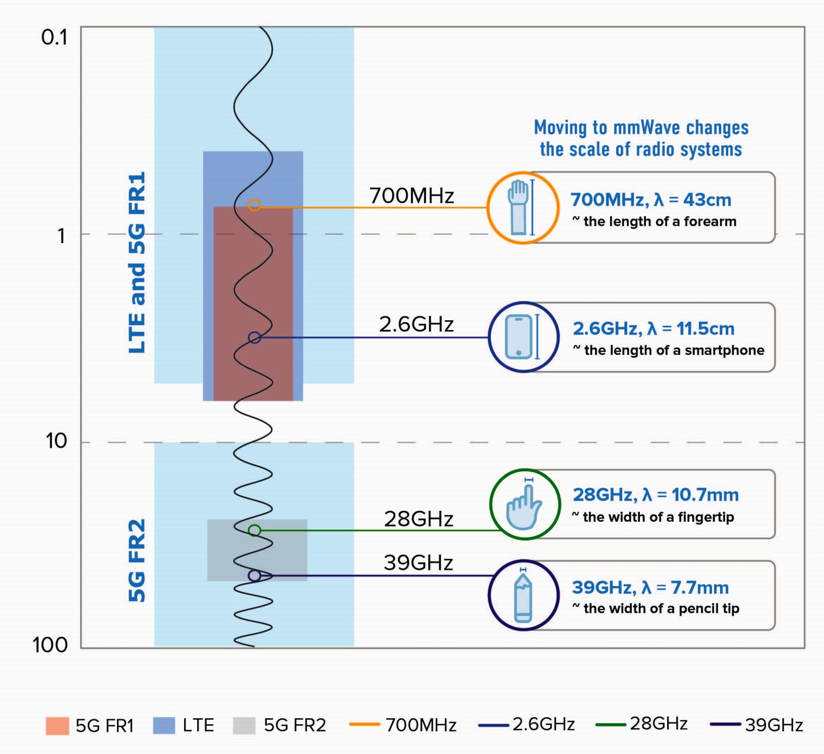
Figure 1. Moving operating frequencies from Sub-6GHz to mmWave leads to numerous RF design challenges.
One RF design challenge at these higher frequencies occurs because these designs require small-form-factor components. You can achieve this without sacrificing performance is to use high K materials. Table 1 compares the difference in size of a sixth order, half-wave resonator filter built using four different materials.
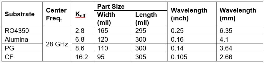
Table 1. Wavelength and size change as Keff increases.
Because size is at a premium in mmWave applications, dimensional tolerances of antenna and filter technologies also become critical. Poor tolerance encroaches on potential board space or layers that could be used for adding other devices or functionality. You can avoid this issue by using a fully integrated design featuring thin-film technology and a high-permittivity dielectric. This approach lets you shrink the overall size and integrate the resistor, reducing variation from resistor tolerances and improving overall RF performance at the lowest cost. Additionally, even though integration of passive functions is not overly difficult at lower frequencies, it can be quite complex at higher frequencies.
Another design issue you’ll encounter in densely packed systems arises because there’s no way to control temperature, which means frequent variations may occur and systems will run hot. Therefore, components such as filters must perform within specification over a wide range of temperatures with a temperature stability of approximately 3 ppm/°C.
Different filter technologies
As you move to FR2, you’ll find different radio architectures that include the number and type of filter technologies. Figure 2 shows the typical frequencies and bandwidths of some standard filter technologies and highlights which overlap with the 5G FR1 and FR2 bands.
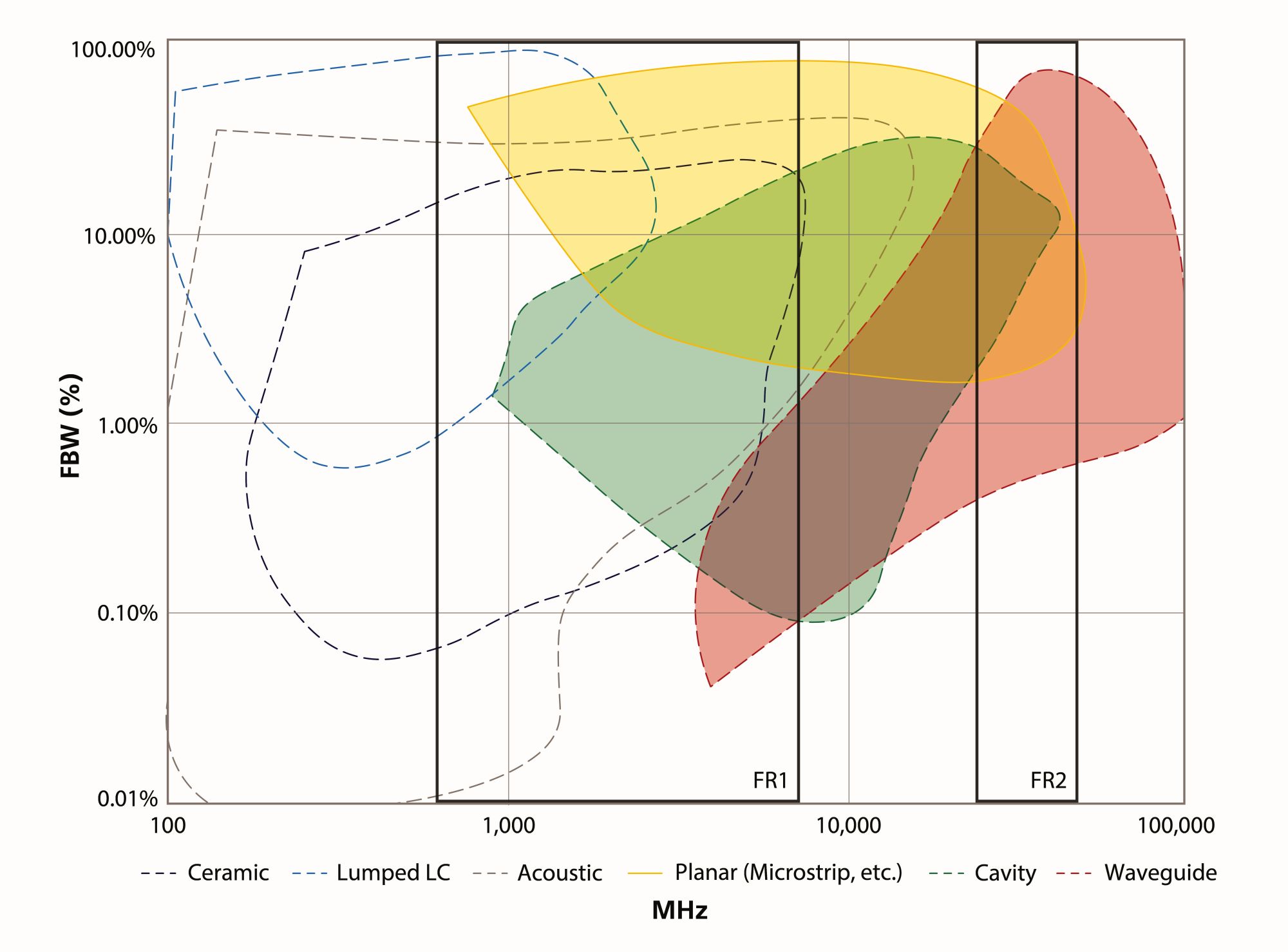
Figure 2. When moving from FR1 to FR2, certain filter technologies need to be left behind in favor of some of the new types of filters available, shown in color.
FR2 brings a change from traditional lumped-element filter designs. In general, the lumped-element model does not work well at higher frequencies because manufacturing the necessary discrete values causes other issues. For example, there are board-level parasitic effects that result from mounting components and the transmission lines used in a lumped element model also result in losses. At high frequencies, these effects would essentially detune a filter.
At RF2 frequencies, RF engineers are shifting to using a distributed element model. As a result, transmission lines and waveguides and their corresponding filtering technologies are the best methods for transferring electromagnetic waves around a circuit. More specifically, a microstrip topology is a great option. If you are unfamiliar with microstrip technology, microstrip refers to a type of planar transmission line consisting of a conducting strip separated from a ground plane by a dielectric substrate (Figure 3).
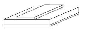
Figure 3. In this microstrip,
the upper substrate is air.
The planar filters used in a microstrip implementation are manufactured using a thin-film process, which offers high Q and a reasonable approach to achieving performance in a small footprint. Planar distributed element filters rely on carefully distributed transmission lines to create resonant structures and can be designed to tighter tolerances than a lumped element filter. This type of planar thin-film implementation is most desirable for mmWave applications from the standpoint of size, cost, and performance.
Making a smooth transition
Even if you’ve been working on RF designs for decades, you should to keep pace with the standards, requirements, and technologies that differ between designing 5G applications that operate sub-6GHz and those at mmWave frequencies.
Instead, to ease this transition, first get to know the 3GPP TS 38.104 V17.2.0 (2021-06) standard. By developing an understanding of these key differences between FR1 and FR2, making the transition to designing mmWave devices will not seem nearly as daunting.
 Peter Matthews is senior technical marketing manager at Knowles Precision Devices. Peter has over 20 years of experience in technology sales, marketing and product management.
Related articles
- System tests 5G devices over the air
- Using online design tools
- 5 things you need to know about 5G filters
- How to Specify a high-frequency PCB
- mmWave signals: The effect on PCB traces, cables and connectors
- Simulate, test, and verify to solve 5G RF design problems
- The complexity of wireless receiver testing