• Skip to primary navigation
  • Skip to main content
  • Skip to primary sidebar
  • Skip to footer

Electrical Engineering News and Products

Electronics Engineering Resources, Articles, Forums, Tear Down Videos and Technical Electronics How-To's

  • Products / Components
    • Analog ICs
    • Battery Power
    • Connectors
    • Microcontrollers
    • Power Electronics
    • Sensors
    • Test and Measurement
    • Wire / Cable
  • Applications
    • 5G
    • Automotive/Transportation
    • EV Engineering
    • Industrial
    • IoT
    • Medical
    • Telecommunications
    • Wearables
    • Wireless
  • Learn
    • eBooks / Handbooks
    • EE Training Days
    • Tutorials
    • Learning Center
    • Tech Toolboxes
    • Webinars & Digital Events
  • Resources
    • White Papers
    • Educational Assets
    • Design Guide Library
    • Digital Issues
    • Engineering Diversity & Inclusion
    • LEAP Awards
    • Podcasts
    • DesignFast
  • Videos
    • EE Videos and Interviews
    • Teardown Videos
  • EE Forums
    • EDABoard.com
    • Electro-Tech-Online.com
  • Bill’s Blogs
  • Advertise
  • Subscribe

Demonstrating antenna diversity, Part 1: The challenges

January 18, 2023 By Bill Schweber Leave a Comment

Antennas come in abroad range of sizes, styles, and configurations to meet frequency, bandwidth, directivity, and many other objectives; the PIGA and Yagi antennas are rather different yet widely used versions.

Fig 1: The half-wave dipole and the quarter-wave monopole antennas are the building blocks which are the basis for nearly all advanced antenna configurations. (Image: EnOcean)

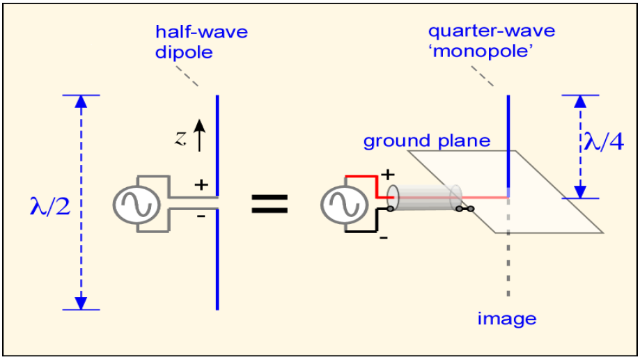
With a few highly specialized exceptions, all antennas in general use – ranging from tiny ones in wearables to huge broadcast-transmitter designs — are extensions, enhancements, and modifications of two basic types. These are the balanced half-wavelength dipole (also called a Hertz antenna) without ground reference, and the electrically unbalanced quarter-wavelength monopole (Marconi antenna) positioned at right angles to a ground plane (Figure 1). [Note: The term “aerial” is used in the United Kingdom and other regions of the world for “antenna” but we will stay with the US-English terminology.]

It’s important to note that there is no such thing as a general “optimum” antenna even within a given configuration, because the needs and priorities of each antenna application differ. Certainly, for most circuit and systems designs, you naturally want to minimize size, weight, and power (SWaP), and cost while maximizing other factors such as speed/performance and reliability. That all makes sense and is logical, to the extent it can be accomplished with the right tradeoffs.

It’s different for antennas. Even within a defined general configuration, what’s “best” depends on the unique demands of the situation. Some applications need a wider bandwidth to capture or transmit signals across a wide spectrum; others must have a narrow bandwidth to minimize noise.

Perhaps the design calls for a very narrow antenna beam width to focus primarily on a targeted receiver (for transmitters) or transmitter (when receiving) while another design for the same center frequency needs a wider bandwidth to reach out broadly. There’s a place and need for each set of performance attributes even if the basic antenna designs are similar. In short, no single antenna type or configuration serves all the needed bands and roles in modern systems, with a large commercial aircraft as an illustrative case (Figure 2).

Boeing 787 antennas
Figure 2. Modern aircraft require a large number and wide range of antenna types to meet the diverse functions and bands these antennas must support. (Image: Boeing via SWLing Post)

By using the two basic antenna types of Hertz dipole and Marconi monopole as starting points, engineers have devised countless variations tailored to the needs and priorities of the application. The complexity is such that here is no single, definitive way to categorize the genealogy of antennas, as their relationships depend to a large extent on the perspective of whoever is drawing that family tree.

Antenna family tree
Figure 3. This antenna “family tree” is just one way of categorizing the genealogy of antenna principles and configurations. (Image: Fayllar.org)

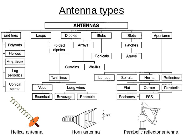
In other words, a diagram made with respect to electromagnetic field principles used in a slotted antenna is different than one which is instead focused on the actual construction via a microstrip antenna but using that principle. The family tree shown in Figure 3 is one good representation.

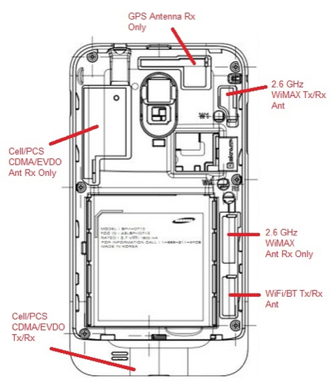
It’s not just systems such as large aircraft that need multiband capabilities, which cannot be met with a single external or internal antenna. Even a somewhat dated smartphone such as the Samsung Galaxy (circa 2011) had to support different frequencies and modes via six distinct antennas. There’s also a bottom conducting plane (the ground plane) as one large plane that extends throughout the length and breadth of the phone. (Figure 4). Of course, the roll-out of 5G — with frequencies ranging from 600 MHz to mmWave — connectivity is adding to the challenge of multiband support.

Samsung phone with antennas
Fig 4: The 2011 Samsung Galaxy S embeds six distinct antennas, as follows: 1: 2.6 GHz WiMAX Tx/Rx Antenna; 2: 2.6 GHz WiMAX Antenna Rx Only (as a diversity antenna); 3: WiFi/Bluetooth Tx/Rx Antenna; 4: Cell/PCS CDMA/EVDO Tx/Rx Antenna; 5: Cell/PCS CDMA/EVDO Rx Only (as a diversity antenna); 6: GPS Antenna Rx Only. (Image: RAYmaps)

Many of today’s devices such as smartphones or the Internet of Things (IoT) require a tiny antenna that fits completely within the small enclosure and must operate on multiple bands. In other cases, the antenna is “out in the open” and so offers the designer many degrees of design freedom.

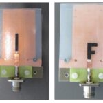
This three-part series will look at two very different and widely used antennas: the planar inverted-F antenna or PIFA (not to be confused with the similar acronym PIGA, the pendulous integrating gyroscopic accelerometer) and the Yagi-Uda antenna (often referred to simply as a Yagi antenna).

EE World Related Content

  • 5 tips for designing with embedded antennas
  • How distributed antenna systems bring cellular indoors
  • The microstrip antenna, Part 1: Basics
  • The microstrip antenna, Part 2: Implementation
  • What materials can be used to make miniature antennas?
  • The basics of dielectric resonator antennas
  • Practicalities of specifying 5G antennas for the IoT
  • How distributed antenna systems bring cellular indoors
  • What to consider when selecting a Wi-Fi antenna


You Might Also Like

Filed Under: 5G, Applications, FAQ, Featured, Wireless Tagged With: FAQ

Reader Interactions

Leave a Reply Cancel reply

You must be logged in to post a comment.

This site uses Akismet to reduce spam. Learn how your comment data is processed.

Primary Sidebar

EE Engineering Training Days

engineering

Featured Contributions

Integrating MEMS technology into next-gen vehicle safety features

Five challenges for developing next-generation ADAS and autonomous vehicles

Robust design for Variable Frequency Drives and starters

Meeting demand for hidden wearables via Schottky rectifiers

GaN reliability milestones break through the silicon ceiling

More Featured Contributions

EE Tech Toolbox

“ee
Tech Toolbox: 5G Technology
This Tech Toolbox covers the basics of 5G technology plus a story about how engineers designed and built a prototype DSL router mostly from old cellphone parts. Download this first 5G/wired/wireless communications Tech Toolbox to learn more!

EE Learning Center

EE Learning Center
“ee
EXPAND YOUR KNOWLEDGE AND STAY CONNECTED
Get the latest info on technologies, tools and strategies for EE professionals.
“bills
contribute

R&D World Podcasts

R&D 100 Episode 10
See More >

Sponsored Content

Designing for Serviceability: The Role of Interconnects in HVAC Maintenance

From Control Boards to Comfort: How Signal Integrity Drives HVAC Innovation

Built to Withstand: Sealing and Thermal Protection in HVAC Sub-Systems

Revolutionizing Manufacturing with Smart Factories

Smarter HVAC Starts at the Sub-System Level

Empowering aerospace E/E design and innovation through Siemens Xcelerator and Capital in the Cloud

More Sponsored Content >>

RSS Current EDABoard.com discussions

  • Safe Current and Power Density Limits in PCB Copper(in A/m² and W/m³) simulation
  • The Analog Gods Hate Me
  • Help with hall effect sensors for a milwuakee impact driver
  • How to find the resonance frequency and impedance of a planar spiral coil in HFSS?
  • Diode recovery test Irrm timing.

RSS Current Electro-Tech-Online.com Discussions

  • Raise your hand if your car had one of these:
  • Simple LED Analog Clock Idea
  • Kawai KDP 80 Electronic Piano Dead
  • Tektronix 2235 channel 1 trace unstable
  • How to make string LEDs?
Search Millions of Parts from Thousands of Suppliers.

Search Now!
design fast globle

Footer

EE World Online

EE WORLD ONLINE NETWORK

  • 5G Technology World
  • Analog IC Tips
  • Battery Power Tips
  • Connector Tips
  • DesignFast
  • EDABoard Forums
  • Electro-Tech-Online Forums
  • Engineer's Garage
  • EV Engineering
  • Microcontroller Tips
  • Power Electronic Tips
  • Sensor Tips
  • Test and Measurement Tips

EE WORLD ONLINE

  • Subscribe to our newsletter
  • Teardown Videos
  • Advertise with us
  • Contact us
  • About Us

Copyright © 2025 · WTWH Media LLC and its licensors. All rights reserved.
The material on this site may not be reproduced, distributed, transmitted, cached or otherwise used, except with the prior written permission of WTWH Media.

Privacy Policy