by Timothy Hegarty, Applications Engineer, Texas Instruments
This article compares electromagnetic interference (EMI) requirements in automotive, industrial, and defense product family standards, specifically various test parameters, test equipment, test setups, and test methods [1-4] for conducted emissions (CEs). The comparison includes widely used dedicated standards in each industry: Comité International Spécial des Perturbations Radioélectriques (CISPR) 25 edition 4 from 2016, a product standard for the protection of onboard receivers in vehicles, boats, and internal combustion engines [5]; CISPR 11 edition 6 from 2015, a product standard for industrial, scientific and medical (ISM) equipment [6] that uses radio-frequency (RF) energy to perform its intended function; and military-standard MIL-STD-461 revision G from 2015, a defense standard for equipment and subsystems enclosures [7-8]. CISPR has subcommittees B and D responsible for CISPR 11 and 25, respectively, whereas the U.S. Department of Defense maintains MIL-STD-461. The European Union adopted CISPR 11 and CISPR 25 as EN 55011 [9] and EN 55025, respectively. CISPR 11 serves extra duty as a basic test method for generic, product, and product-family emissions standards, such as the generic emissions standard for industrial environments, International Electrotechnical Commission (IEC) 61000-6-4 [10].
CE test setups and methods
- Applicability and test frequency ranges
Components and modules intended for onboard automotive applications are tested according to CISPR 25 over a total frequency range of 150 kHz to 108 MHz to protect onboard receivers in the broadcast and mobile services frequency bands.
Testing in the CISPR band B frequency range of 150 kHz to 30 MHz in accordance with the scope of CISPR 11 (or Federal Communications Commission part 18 in the U.S.) fulfills the CE requirements for products manufactured in ISM applications.
In MIL-STD-461G, carrying out CE101 and CE102 tests in the frequency range of 30 Hz to 10 kHz and 10 kHz to 10 MHz, respectively, fulfills CE requirements. These tests are carried out on the power leads, including returns of the equipment under test (EUT) that obtain power from external (mains or DC) power sources. The applicability of the tests depends on the equipment’s intended installation environment.
- Test equipment
The primary test equipment required to conduct CE tests includes:
- An EMI receiver or spectrum analyzer – with the appropriate peak (PK), quasi-peak (QP) or average (AV) detector as defined in CISPR 16-1-1.
- A line impedance stabilization network (LISN) – otherwise known as an artificial mains network (AMN), artificial network (AN) or V-network.
- A current probe – only required for the current method test in CISPR 25 and the CE101 test in MIL-STD-461.
More specifically, the LISN is a passive network that provides a definite and constant termination impedance (close to 50 Ω) across the EUT power terminals over the applicable test frequency range dictated by each standard. It is also useful to isolate the EUT from ambient noise on the respective AC or DC power lines over the test frequency range. The RF port of the LISN connects to the 50-Ω input port of the EMI receiver to measure the noise generated by the EUT.
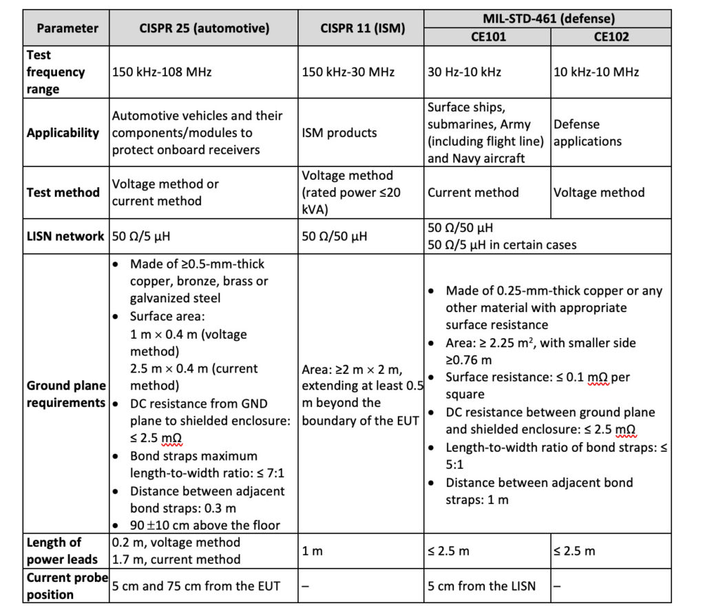
Table 1 details the applicable frequency ranges for different applications. The table includes a comparison of various test parameters such as test frequency range, LISN network type, test equipment and test setup requirements.
The measurement receiver should be able to sweep in the required test frequency range with the appropriate resolution bandwidth (RBW) provided in the respective standards for different applications. To that end, Table 2 gives the detector type, RBW, measurement step size and dwell-time parameters for the EMI receiver.

The LISN networks specified in different standards are not the same, since the test frequency ranges differ. Figures 1, 2 and 3 show the network schematic and nominal impedance curve of LISNs intended for CISPR 25, CISPR 11 and MIL-STD-461 measurements, respectively. The LISN for CISPR 11 in Figure 2 is a V-network (V-AMN) as specified in CISPR 16-1-2 [11] for line-to-ground unsymmetric mode emissions at a low-voltage AC mains power port.
(Using a specialized 150-Ω artificial mains Δ-network specified in clause 4.7 of CISPR 16-1-2 [see also Figure A.2 in CISPR 16-1-2] or the 150-Ω artificial DC network [DC-AN] specified in annex I of CISPR 11 facilitates CISPR 11 measurement of the disturbance voltages at a low-voltage DC power port [for example, grid-connected solar inverters]. Both couple the line-to-line or symmetric (differential-mode) and asymmetric (common-mode) voltage disturbances separately, where typically a switch enables you to select each disturbance mode as needed.
In general, terminating the measurement port with a 50-Ω load takes the impedance of the LISN (as shown in Figures 1, 2 and 3) between the output and ground. This standardized impedance represents the expected impedances in actual installations.


A LISN inductance of 50 µH represents the inductance of power distribution wiring running for approximately 50 m. For a large platform (such as a cargo aircraft or an industrial system), this value is quite representative of the actual installation. For smaller platforms (such as fighter aircraft) where the power distribution wiring has short lengths, the inductance values may be substantially lower than 50 µH.
MIL-STD-461 specifies the use of a default 50-µH LISN as shown in Figure 3a, but it also supports the use of a 5-µH LISN (similar to that in Figure 1a) for certain applications where high-current loads exist, where power distribution wiring has short lengths, or where dedicated returns run with the high-side power connections (as opposed to a structure return). The 5-µH LISN in these cases must be approved by the procuring activity, with necessary adjustments to the CE101 test limits.
Meanwhile, automotive applications use a lower inductance LISN of 5 µH, as that simulates the typical inductance of an automotive harness setup.
- Test setup requirements
- Reference ground plane
Made of copper, brass, bronze or galvanized steel, the ground plane electrically bonds to the walls or the floor of the shielded enclosure such that its DC resistance does not exceed 2.5 mΩ. The minimum sizes of the ground plane are specified as 1 m by 0.4 m, 2.5 m by 0.4 m, 2 m by 2 m and 2.25 m2 according to the CISPR 25 voltage method, CISPR 25 current method, CISPR 11 and MIL-STD-461 standards, respectively.
- EUT and LISN placement
The EUT is placed on a nonconductive, low relative permittivity material (er ≤ 1.4), positioned at a height of (50 ±5) mm above the reference ground plane per CISPR 25 and MIL-STD-461 standards and 400 mm above the ground plane per the CISPR 11 standard (for non-floor-standing equipment). The EUT should be bonded to the ground plane if it is bonded in the actual installation. The LISN mounts on the ground plane and bonds electrically to it.
- Test methodology (voltage or current method)
Two methods are possible when performing a CE test: a voltage method and a current method. With the voltage method test, the LISN, which connects to the power lead under test, acts as transducer; its RF measurement port connects to the input port of a measurement receiver. The RF port of the other LISN in the test setup is terminated with a 50-Ω load. With the current method test, the current probe clamps on the power lead under test and acts as a transducer to measure the noise current flowing through the lead.
The CISPR 25 standard allows either a voltage method or current method test. The CISPR 11 standard calls for a voltage method test when power levels are less than 20 kVA. The CE101 and CE102 tests in MIL-STD-461 use a current method and voltage method test, respectively.
For all tests, the conducted electromagnetic ambient level is measured before conducting the test with the EUT deenergized and all auxiliary equipment in a turned-on condition. It should be at least 6 dB below the allowable specified limits.
- Placement and length of the power cables
The power leads that run from the EUT to the LISN power port are placed over a nonconductive support at a height of 50 mm above the reference ground plane for CISPR 25 and MIL-STD-461.
Using the voltage test method, the lengths of the power leads are 0.2 m, 1 m and 2 m, as defined by the CISPR 25, CISPR 11 and MIL-STD-461 standards, respectively. When using the current method, the cable harness according to CISPR 25 runs 1.7 m long (or as agreed upon in the test plan). The test harness wires are set nominally parallel and adjacent – again unless otherwise defined in the test plan. The power leads for the CE101 test procedure in MIL-STD-461 run for at least 2 m, and the current probe for CE101 positions at 5 cm from the LISN.
- Detector types
CISPR 25 uses PK or QP and AV detectors, CISPR 11 uses QP and AV detectors, and MIL-STD-461 calls for a PK detector to carry out the CE test.
CE limits and setups
- CISPR 25 (voltage and current methods)
Figure 4 shows the CISPR 25 Class 5 PK and AV limits for CE disturbances across broadcast and mobile service bands using voltage and current test methods. Red and blue lines denote PK and AV detectors, respectively.
Since the mounting location, vehicle body construction and harness design can affect disturbance levels to onboard radio receivers, CISPR 25 delineates multiple limit levels, with Class 5 being the most stringent. Classes 4, 3, 2 and 1 have 6- to 10-dB progressively higher limits.

Figures 5 and 6 show the CE test setups recommended by CISPR 25 for the voltage and current methods, respectively. This standard defines the disposition of the system under test and the measurement protocols and equipment. The LISN is designated by CISPR 25 as an AN. The AN(s) are mounted directly on the reference ground plane, with the AN case(s) bonded to the ground plane. The power-supply return also connects to the ground plane between the power supply and the AN.
For the voltage method test depicted in Figure 5, the EUT is remotely grounded when the vehicle power return line is longer than 200 mm, and two ANs are required: one for the positive supply line and one for the power return line. Conversely, if the vehicle power return line is 200 mm or shorter, the EUT is locally grounded with only one AN required for the positive supply. Connecting the EMI receiver at the measuring port of the corresponding AN enables successful measurement of the emissions conducted on each power line. Meanwhile, a 50-Ω load terminates the port of the AN inserted in the other power line. The power-supply lines are placed in a straight line on a nonconductive, low-relative-permittivity material (er < 1.4) at 50 mm above the reference ground plane.

For the current method, the test setup depicted in Figure 6 simulates the actual vehicle configuration, which dictates remote versus local grounding as well as the electrical connection of the EUT case to the reference ground plane. The current probe, defined in CISPR 16-1-2, mounts around the complete harness, including all wires, and locates in two positions, 5 cm and 75 cm from the EUT. The shielded harness used for this test is representative of the vehicle application in terms of cable construction and connector termination, as defined in the test plan.

- CISPR 11
CISPR 11 is concerned with the control of RF disturbances from ISM equipment by assessing these disturbances either at a standardized test site or, for an individual ISM RF application that cannot be tested at such a site, at its place of operation (in situ). In order to identify relevant limits, equipment within the scope of this standard is organized into two groups:
- Group 1 contains all equipment in the scope of CISPR 11 that is not classified as Group 2 equipment (examples include semiconductor manufacturing equipment, machine tools, and industrial process measurement and control equipment). See annex A of CISPR 11 for more detail.
- Group 2 contains all ISM equipment in which RF energy in the frequency range of 9 kHz to 400 GHz is intentionally generated and used locally. Examples include arc welders and wireless power transfer systems.
Furthermore, each equipment group has Class A (nonresidential, industrial, commercial) and Class B (residential, consumer) designations with relevant limits.
Figure 7 shows the CISPR 11 limit lines for group 1 (AC mains and DC power ports) and group 2 (AC mains power port) equipment. Red and blue lines refer to QP and AV detectors, respectively. See Tables 2 and 5 (group 1) and Tables 8 and 9 (group 2) of the CISPR 11 publication for additional context [9]. Figure 8 shows a CE test setup with a bench-mounted EUT.


- MIL-STD-461 (CE101 and CE102)
Figure 9 gives the limits for CE101 (audio-frequency currents, power leads) and CE102 (RF potentials, power leads) using a PK detector. See the MIL-STD-461 specification to gain more insight into limit relaxations under various conditions.

As depicted in Figure 10, input power leads 2 m in length (including neutrals and returns) are routed parallel to the front edge of the setup for CE101 and CE102 tests in MIL-STD-461. Each input power lead connects to a LISN.
The power leads that are bundled as part of an interconnecting cable in the actual installation are separated from the bundle and routed to the LISNs – outside the shield of shielded cables. After the exposed length of 2 m, the power leads terminate at the LISNs in as short a distance as possible. The total power lead length from the EUT electrical connector to the LISNs should not exceed 2.5 m – except for large EUTs as depicted in Figure 10b, where the cables are routed from the top of a tall EUT or from the bottom of a floor-standing cabinet. In that case the total length may then exceed 2.5 m, but is still kept to a minimum. All power leads are supported 5 cm above the ground plane with nonconductive material, typically foam or wood. The power leads are twisted up to the LISNs if there is a twisted connection in the actual installation.

Summary
This article explained the similarities and differences in various EMI test parameters, test equipment, test setups and test methods for CE testing within the purview of CISPR 25, CISPR 11 and MIL-STD-461 for automotive, industrial and defense applications, respectively [13-15]. A particular subsystem or equipment complying with these requirements should function in its intended electromagnetic environment within its designated design tolerances.
References
- Hegarty, Timothy. 2018. “An overview of conducted EMI specifications for power supplies.” Texas Instruments white paper, literature No. SLYY136, February 2018.
- Hegarty, Timothy. 2021. “An engineer’s guide to EMI in DC-DC regulators.” Texas Instruments e-book, chapter 1, Q2 2021 (pending).
- Chaluvadi, Mahesh, G. Vincentraj and K. George Thomas. “A comparison study on conducted emission test in international EMC standards.” Published in IEEE International Conference on Power, Control, Signals and Instrumentation Engineering, Sept. 21-22, 2017, pp. 1352-1355.
- Chaluvadi, Mahesh, G. Vincentraj and K. George Thomas. “An insight into MIL-STD-461G: a study report.” Published in IEEE International Conference on Power, Control, Signals and Instrumentation Engineering, Sept. 21-22, 2017, pp. 1356-1359.
- “Vehicles, boats and internal combustion engines – Radio disturbance characteristics – Limits and methods of measurement for the protection of on-board receivers.” CISPR 25:2016, fourth edition (or EN 55025:2017). CISPR: Geneva, Switzerland, October 2017.
- “Industrial, scientific and medical equipment – Radio-frequency disturbance characteristics – Limits and methods of measurement.” CISPR 11:2015, sixth edition. CISPR: Geneva, Switzerland, January 2019.
- “Requirements for the control of electromagnetic interference characteristics of subsystems and equipment.” MIL-STD-461G, U.S. Department of Defense Interface Standard: Washington, DC, December 2015.
- Javor, Ken. 2018. “E Pluribus Unum – A look back at fifty years of MIL-STD-461.” Interference Technology magazine, 2018 Directory and Design Guide.
- “Industrial, scientific and medical equipment – Radio-frequency disturbance characteristics – Limits and methods of measurement.” IS EN 55011:2016, European norm standard based on CISPR 11. European Committee for Electrotechnical Standardization (CENELEC): Brussels, Belgium, 2016.
- “Electromagnetic compatibility (EMC) – Part 6-4: Generic standards – Emission standard for industrial environments.” IEC 61000-6-4, third edition. IEC: Geneva, Switzerland, February 2018.
- “Specification for radio disturbance and immunity measuring apparatus and methods – Part 1-2: Radio disturbance and immunity measuring apparatus – Coupling devices for conducted disturbance measurements.” CISPR 16-1-2:2014. CISPR: Geneva, Switzerland, August 2020.
- “Specification for radio disturbance and immunity measuring apparatus and methods – Part 2-1: Methods of measurement of disturbances and immunity – Conducted disturbance measurements.” CISPR 16-2-1:2014. CISPR: Geneva, Switzerland, June 2017.
- “2020 Automotive EMC Guide.” Interference Technology magazine, May 2020.
- “2020 Medical EMC Guide.” Interference Technology magazine, September 2020.
- Ferguson, Steve. 2020. “MIL-STD-461G and RTCA/DO-160G test configuration management.” 2020 Military and Aerospace EMC Guide, Interference Technology magazine, December 2020, pp. 8-12.

