Understanding how filters are characterized is the first step in choosing an appropriate topology with suitable specifications.
Filters are both a simple and also complicated and often confusing topic. This part clarifies some of the issues.
Q: Why are so many discussions about filters so confusing?
A: There are many reasons, but one is that filters are called out from different perspectives depending on the application and who is describing it. These overlapping perspectives include:
- basic function such as low pass, for example.
- a key characteristic, such as maximally flat.
- equations which describe the filter transfer function, such as Butterworth, Bessel, Sallen-Key, or elliptical.
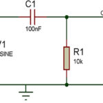
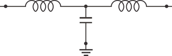
- the overall appearance of the filter’s schematic diagram, such a π-filter (has nothing to do with Greek letter pi, it’s just the arrangement of components on the diagram look like that letter) (Figure 1).

- the role of the filter in the circuit, such as 56/60-Hz noise rejection.
Q: Which of the above is the primary description of a given filter?
A: All of the above: it depends on the historical role and the immediate application.
Q: What happens to the signal energy which the filter rejects?
A: The answer is simple: it is dissipated as heat. For low-level signals under a few hundred milliwatts, this heat is generally not an issue. At higher power levels of several watts and into kilowatts (and there are kilowatt filters), the filter’s components must handle that heat. The system must be able to dissipate the heat the filter dissipates. This complicates design to some extent and construction to a larger extent.
Q: What is filter “order”?
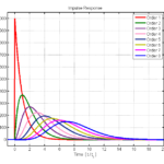
A: The order refers to the polynomial, which describes the filter’s transfer function. It also refers to the number of physical stages of the filter circuit. A basic first-order filter has one stage, while higher-order filters have more stages and can yield higher figures of performance merit, but at a cost in components and complexity.
Q: What’s the difference between a passive filter and an active one?
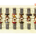
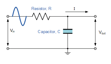
A: Passive filters are built from only the three key passive components: resistors, inductors, and capacitors (Figure 2); many filters use just two of the three, such as RC or LC. These RLC filters also introduce a loss in the sign path (attenuation) due to the inherent dissipation of a resistor as well as resistive, non-ideal aspects of the inductors and capacitors.
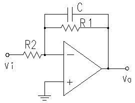
In contrast, an active filter uses one or more gain components, usually operational amplifiers (op amps), to boost signal strength as it passes through the filter. As a result, the signal output is not attenuated and can even be boosted relative to its input level.
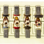
But an active filter is much more than a passive filter with signal boosting – that could be achieved simply by adding an amplifier at the filter output. Instead, adding internal amplifiers enables new filter topologies and transfer functions which cannot be achieved easily or at all by using only passive components (Figure 3).
Q: What’s the broad difference between an analog filter and a digital filter?
A: An analog filter, whether passive or active, uses only analog components (RLC, op amps) and acts on the signal as that signal passes through it. For that reason, it is sometimes called a continuous-time filter.
A digital filter, sometimes called a sampling or discrete filter, periodically samples the signal of interest, digitizes the sampled signal, then numerically processes the sampled data via a programmed algorithm. In some cases, the processed digital output is converted back to analog. In many cases, though, the digitally filtered output is used “as is” by the system’s software with no need to re-convert it.
Q: Which filter is better: analog or digital?
A: Neither is an inherently better approach: they are different types of filtering, and each is best suited for different classes of applications. For example, an analog filter is the better choice by far to filter out 50/60Hz AC-line noise. However, a digital filter is better to implement sophisticated filtering of many channels in a wideband receiver and jumping among those channels. The math behind each one is quite different as well.
Digital filters are software (firmware) driven, so they can be tuned and adjusted via a keyboard until they are just right. Their algorithm can even be set up to dynamically adjust and modify its filtering parameters in real-time during the course of operation for even better system-level performance.
Q: Are there different broad classes of digital filters?
A: Yes, digital filters come in two classes. One is finite impulse response (FIR), and the other is infinite impulse response (IIR). The former is a digital implementation of an analog filter, even a complicated one. The latter is unique because it cannot be realized using physical components yet offers attractive filter attributes in some cases.
The next part of this article looks at some of the fundamental parameters used when specifying or choosing analog filters and, to a lesser extent, digital filters.
Related EE World Content
- A scope-based technique for optimizing EMI input filters
- 5G RF filters need more innovation
- Filters offer ‘brick-wall’ performance to 7 GHz for semiconductor and IC testing
- Basics of audio filters
- What are switched capacitor filters, amplifiers and integrators?
- How to design modular DC-DC systems, Part 2: Filter Design
- RF/Microwave bandpass filter implementations, Part 1: Distributed filters
- RF/Microwave bandpass filter implementations, Part 2: Cavity and comb filters
- RF/Microwave bandpass filter implementations, Part 3: Microstrip, Coaxial, and helical filters
- Filters, Part 1: Analog, switched, and digital filters
- Filters, Part 2: SAW and BAW devices for RF
- 5 things you need to know about 5G filters
External References (note: Most of these are “equation-light” references)
- Student Circuit, “Electronic Filter”
- All About Circuits, “An Introduction to Filters”
- ElectronicFundablog, “Filters – Classification, Characteristics, Types, Applications & Advantages”
- Electrical Technology, “Types of Filters and Their Applications”
- Electronics Tutorials, “Passive Low Pass Filter”
- Wikipedia, “Electronic Filter”
- Wikipedia, “Low-pass filter”
- Wikipedia, “RC Time Constant”
- Thor Labs, “Relationship Between Rise Time and Bandwidth for a Low-Pass System”
- Georgia State University, “Filter Circuits”
- Wiki Lectures, “Time constant and filters”
- Coilcraft, “Filter LC responses”
- Swarthmore College, “Frequency Response and Active Filters”
- EL-PRO-CUS, “Tutorial on Different Types of Active Filters and Their Applications”
- Technobyte, “Filter Approximation and its types – Butterworth, Elliptic, and Chebyshev”
- Embedded Related, “First-Order Systems: The Happy Family”