• Skip to primary navigation
  • Skip to main content
  • Skip to primary sidebar
  • Skip to footer

Electrical Engineering News and Products

Electronics Engineering Resources, Articles, Forums, Tear Down Videos and Technical Electronics How-To's

  • Products / Components
    • Analog ICs
    • Battery Power
    • Connectors
    • Microcontrollers
    • Power Electronics
    • Sensors
    • Test and Measurement
    • Wire / Cable
  • Applications
    • 5G
    • Automotive/Transportation
    • EV Engineering
    • Industrial
    • IoT
    • Medical
    • Telecommunications
    • Wearables
    • Wireless
  • Learn
    • eBooks / Handbooks
    • EE Training Days
    • Tutorials
    • Learning Center
    • Tech Toolboxes
    • Webinars & Digital Events
  • Resources
    • White Papers
    • Design Guide Library
    • Digital Issues
    • Engineering Diversity & Inclusion
    • LEAP Awards
    • Podcasts
    • DesignFast
  • Videos
    • EE Videos and Interviews
    • Teardown Videos
  • EE Forums
    • EDABoard.com
    • Electro-Tech-Online.com
  • Bill’s Blogs
  • Advertise
  • Subscribe

Analog Top Talks in December on EDABoard.com forums

January 3, 2019 By Aimee Kalnoskas Leave a Comment

Peer-to-peer, engineer-to-engineer questions and answers from the EDABoard.com engineering community around analog ICs and analog design. Click the “Read more” link and follow the entire conversation and maybe add your two cents by logging in to EDAboard.com.

Signal integrity problem in a 100MHZ CLK –  I am wondering about a signal integrity issue with a 100MHz clock generated by an FPGA. This is the set up:
– FPGA generates a 100MHZ square signal with 50% of duty cycle.
– The IO constraint is LVCMOS 3.3V.
– The PCB track has a length of 20cm, and it finished in a Sub-D25 connector. The track has a series termination resistor (Rt). Read more

P-mos not turning off – The p-mos(U1) remains OFF initially when n-mos(Q1) is OFF. Once, a signal from n-mos(Q1) is sent, the p-mos(U1) turns ON, but, even after turning OFF the n-mos(Q1), p-mos(U1) remains ON. Can anyone tell me the reason? Read more


Tuning of transconductance in OTA circuit – I want to tune the transconductance of OTA. For transconductance tuning I have to vary the biasing current. But how can I vary the biasing current what circuitry should be used to vary the biasing current for transconductance tuning. Read more

PLL and DLL and their differences?  – I want to become intimate with the PLLs and DLLs. I think the best way is to design and operate them in simulation and on bench. However, I am not sure where to start. It is possible to create them in MATLAB Simunlink (maybe) to learn about how the mechanism works. But I don’t know if they can be constructed using different components on bench or can only work in an integrated circuit. Read more

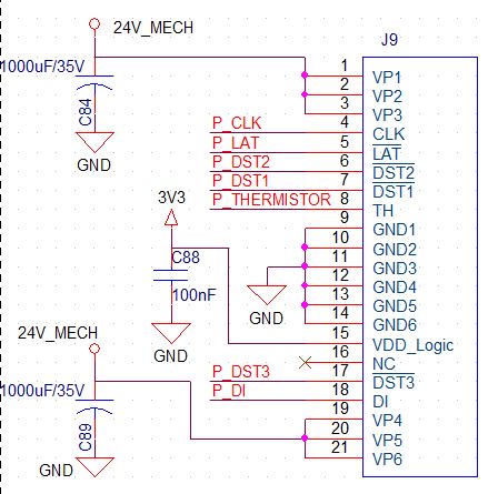
Workaround for power supply not local with receiver input – I’m stuck with an issue. A 0 – 5V 33Hz pulse train needs to be interfaced with an optocoupler 4N46 before it reaches to a DAQ input. This needs to block common mode EMI which introduces noise at this DAQ‘s input. Read more

Folded cascode amplifier is an op-amp or OTA? – I want to know if a folded cascode amplifier is an OTA or opamp. Read more

Distorted sine output from transformer – I am using an amplifier (LT1210) with +-15V supply and its output is connected to a transformer RM10 core N97 with 9:150 step-up ratio and its output has to be connected to various piezoelectric transducers in the range 40 to 300 kHz and impedances varying from 20 to 2.5kΩ. The problem is I can’t amplify my signal as much as I want to as the sine wave gets distorted and also I have to connect a resistor between amplifier and transformer to make this circuit work. Read more

Slew rate and slew rate limiting –  If the value of the maximum change of the output of the opamp is greater than the slew rates positive and negative (single-ended output) – then I don’t get slew rate limiting OR is it less than the positive and negative slew rates? Read more

5-decade precision current sense application – I’m concepting a current sense application covering about 5 decades from 500μ to 5A where high precision <0.1% AC/DC and high bandwidth ~1Mhz are required (high precision applies to <<1mhz). Ultimately the signal is fed to an ADC (>5MSPS). So first I think it’s obvious this requires multiple shunts and my thought is to space them every decade -> 0.01/0.1/1/10/100.  Read more

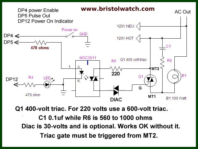
Arduino controlled light dimmer – Working on an urgent project of a light dimmer that starts low and the gets brighter in 4 steps — 5% glow then 20% then 50% then 80% or even gradually still good. I found the circuit below at this great website. The light power I need is 3000 W. Can I simply replace the Triac with a bigger power like BTA41-600V? Or do I need to make other changes on the circuit? Read more

analog

You Might Also Like

Filed Under: EE Forums, Featured Tagged With: EDAboard.com, edaboardcom

Reader Interactions

Leave a Reply Cancel reply

You must be logged in to post a comment.

This site uses Akismet to reduce spam. Learn how your comment data is processed.

Primary Sidebar

EE Engineering Training Days

engineering

Featured Contributions

Meeting demand for hidden wearables via Schottky rectifiers

GaN reliability milestones break through the silicon ceiling

From extreme to mainstream: how industrial connectors are evolving to meet today’s harsh demands

The case for vehicle 48 V power systems

Fire prevention through the Internet

More Featured Contributions

EE Tech Toolbox

“ee
Tech Toolbox: Internet of Things
Explore practical strategies for minimizing attack surfaces, managing memory efficiently, and securing firmware. Download now to ensure your IoT implementations remain secure, efficient, and future-ready.

EE Learning Center

EE Learning Center
“ee
EXPAND YOUR KNOWLEDGE AND STAY CONNECTED
Get the latest info on technologies, tools and strategies for EE professionals.
“bills

R&D World Podcasts

R&D 100 Episode 10
See More >

Sponsored Content

Advanced Embedded Systems Debug with Jitter and Real-Time Eye Analysis

Connectors Enabling the Evolution of AR/VR/MR Devices

Award-Winning Thermal Management for 5G Designs

Making Rugged and Reliable Connections

Omron’s systematic approach to a better PCB connector

Looking for an Excellent Resource on RF & Microwave Power Measurements? Read This eBook

More Sponsored Content >>

RSS Current EDABoard.com discussions

  • Elektronik devre
  • Powering a USB hub: safely distributing current from a shared power supply
  • RF-DC rectifier impedance matching
  • How can I get the frequency please help!
  • 12VAC to 12VDC 5A on 250ft 12AWG

RSS Current Electro-Tech-Online.com Discussions

  • 100uF bypass Caps?
  • Fuel Auto Shutoff
  • Actin group needed for effective PCB software tutorials
  • how to work on pcbs that are thick
  • compatible eth ports for laptop
Search Millions of Parts from Thousands of Suppliers.

Search Now!
design fast globle

Footer

EE World Online

EE WORLD ONLINE NETWORK

  • 5G Technology World
  • Analog IC Tips
  • Battery Power Tips
  • Connector Tips
  • DesignFast
  • EDABoard Forums
  • Electro-Tech-Online Forums
  • Engineer's Garage
  • EV Engineering
  • Microcontroller Tips
  • Power Electronic Tips
  • Sensor Tips
  • Test and Measurement Tips

EE WORLD ONLINE

  • Subscribe to our newsletter
  • Teardown Videos
  • Advertise with us
  • Contact us
  • About Us

Copyright © 2025 · WTWH Media LLC and its licensors. All rights reserved.
The material on this site may not be reproduced, distributed, transmitted, cached or otherwise used, except with the prior written permission of WTWH Media.

Privacy Policy