An attenuator is a four-terminal, two-port network that reduces the amplitude of a signal without distorting its waveform. Attenuators are used in electronic instrumentation to precondition a signal for measurement and display. For example, the commonly-used 10:1 oscilloscope probe attenuates the signal voltage upstream from the analog channel input by a factor of ten, letting the user display signal amplitudes exceeding the instrument’s rating.
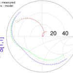
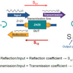
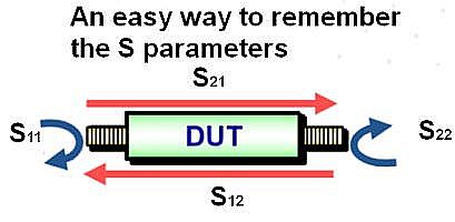 All attenuators have an associated insertion loss. In that many attenuators are designed to operate in the RF range, their insertion loss is often characterized by a complex impedance. For accuracy, this insertion loss is generally measured using a network analyzer. Thus the loss is represented by the S-parameter S21 measured via a two-port connection.
In a typical measurement, the network analyzer makes a full set of S parameter measurements on the DUT for 0 dB attenuation, saving the value as the reference insertion loss. The S parameter measurements then are repeated for each attenuator setting. The values of S21 are adjusted for reference S21 values measured for 0 dB attenuation. The difference is the attenuation accuracy. Some commercial attenuators include an on-board EEPROM holding correction factors, in which case the corrected S21 values are usually written to EEPROM.
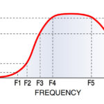
Similarly, attenuators operating in the RF range also have a return loss, characterized by S11 or S22. Of course, return loss varies with frequency when the attenuator contains impedances. So for wide frequency ranges, the characterization of return loss can take time. One practice is to develop a frequency offset table consisting of the frequency and attenuation points to determine the attenuator performance across the frequency sweep of interest.

Perhaps the most common use for attenuators is in power measurements. In this case the attenuator has to handle the maximum and minimum output power levels of the DUT. In particular, the attenuator must be able to handle max levels for signals having a high crest factor.
The amount of attenuation is equal to the output/input ratio, which is always less than one. However, voltage attenuation is more conveniently measured according to the logarithmic decibel scale, given by the equation
dBV = 20 log10 Vout/Vin. Of course, all dB measurements must assume a reference point. In rating a passive attenuator, the reference point is 0 dB.
 There are three principal passive attenuator configurations named after letters that their schematics resemble: L, T, and π. Each of these configurations can be either balanced or unbalanced. The balanced counterpart of the T-pad attenuator is known as an H-pad. Another variation is the bridge T-pad. The balanced π-pad is an O-pad.
In balanced attenuators, additional impedances are connected across the transmission line. The ground is then located at a center point with respect to the balanced parallel impedances.
The simplest attenuator is the L-pad, which is merely a four-terminal, two-port voltage divider comprised of two impedances. In an audio system, the L-pad attenuator is often used to reduce a signal that would otherwise overwhelm the speaker, and also to match the source and load impedances for maximum power transfer. If, however, source and load impedances are different, the attenuator can be designed to match one or the other, but not both. For this reason, the L-pad is considered an asymmetrical attenuator. To match two unequal impedances, symmetrical attenuators such as the T-pad or the π-pad are used.
The T-pad passive attenuator consists of three resistors, two in series with the input and output, and a third resistor located in parallel with the input and output, from the center connection of the two series resistors to the ground return line.
The T-pad attenuator has the same impedance looking from either end. Because its design is symmetrical, it is a more versatile impedance-matching device. Input and output may be transposed. It can be used to match either equal or unequal transmission lines. The two series resistive elements generally have the same value. But they can have different values if intended to join circuits that have different impedances. When used to match unequal impedances, the T-pad attenuator is known as a taper-pad attenuator.
The balanced T-pad attenuator is comprised of two equivalent T-pads connected together, sharing in common the same two series resistors with ground center points that are in parallel with input and output. This combination forms a single four-terminal, two-port passive attenuator. The balanced T-pad attenuator is known as an H-pad attenuator because its schematic resembles that letter.
The bridged T-pad attenuator uses an additional resistor in the series line. Notice that it bridges (i.e. is connected in parallel across) the two series-connected resistors.
The bridged T-pad attenuator reduces the signal by altering the characteristic impedance of the circuit. That is because the signal flies across the T-pad attenuator. The two original T-pad resistive elements remain equal to the input and output impedances. You could say that the bridged-pad matches itself to the characteristic impedance of the two transmission lines.
Additionally, it is feasible to substitute a potentiometer or a resistive switch for two of the resistive elements, thereby creating a variable attenuator network. Rather than using a potentiometer, a stepped bridged-T attenuator can be created by using switched, fixed value resistors.
The π-pad passive attenuator schematic generally consists of one series impedance element. On the input and output sides are two impedance elements connected in parallel to the ground return line. The π-pad attenuators are used in RF and microwave transmission lines. At these frequencies it is essential to avoid the use of any inductive elements such as wire-wound resistors. The π-pad attenuators are available in unbalanced and balanced configurations. They are symmetrical and can be used between equal or unequal impedances as matching devices. When configured between circuits of equal impedance, the impedance elements have the same value, but to match circuits of unequal impedance, different values are chosen.
The balanced π-pad attenuator requires an additional impedance in the common ground line, and for that reason it is called an O-pad attenuator. In the O (balanced) configuration, the value of the upper series impedance is divided by two, as is the lower series impedance. Now that there are two half-valued series impedances, however, the overall series impedance remains the same as in the π-pad configuration.
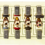
Attenuators are balanced or unbalanced depending upon the type of transmission line. For example, attenuators used with coaxial lines are unbalanced. Attenuators used with unshielded twisted pairs as in Ethernet circuits are balanced. Because most attenuator circuits consist only of passive elements, they are linear as well as reciprocal. If the circuit is symmetrical, then input and output ports may be reversed. RF attenuators generally take the form of precision coaxial connectors. Waveguides are required for frequencies in excess of 30 GHz, with wavelengths less than one centimeter.
An optical attenuator, of which a fiber optic attenuator is a special case, reduces the power level of an optical signal. You can make a continuously variable, free-space (non-fiber) optical attenuator by removing the lenses from a pair of polarized sunglasses. When held together so the polarizing lines are parallel, all incident light will pass through and attenuation is minimum. When held so that the polarizing lines are perpendicular, no light passes and attenuation is maximum. When rotated, attenuation varies between these extremes.
In fiber optic communications, an optical attenuator can be installed inline to match signal levels, preventing harmful reflections and data loss. Optical attenuators can also be inserted temporarily to test optical power levels. Various expedients involve introducing a small gap by loosening a connector, although this can cause reflections. Another quick solution is to wrap several turns of optical fiber around a pencil so a portion of the light is not conveyed by means of total internal reflection.