Thermal management is a critical element in all types of electronic equipment. There are three general aspects to thermal management; heat transfer, temperature measurements, and managing the coefficients of thermal expansion of the various materials and components used in an electronic assembly.
At the most basic level, thermal management involves applying the science of heat transfer to maintain the operating temperature of the equipment within acceptable bounds. Heat transfer science studies the energy transfer between two bodies due to temperature differentials. There are three mechanisms of heat transfer; conduction, convection, and radiation.
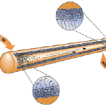
Thermal conduction occurs when there is a temperature gradient across a body. With conduction, the thermal energy is transferred through diffusion from a high-temperature region to low temperature region. Thermal convection comprises two mechanisms, diffusion plus the transfer of energy to a cooling fluid (this can be air or various liquids) as it passes over the warm body. Convection cooling can be classified by how the cooling fluid passes across the surface to be cooled. In natural convection, cooling the fluid flowing across the warm body heats, reducing its density and causing it to rise and flow across the surface. In the case of forced convection, the cooling fluid is moved using a fan, pump, or another mechanical system. Finally, thermal radiation is the cooling effect, where the heat energy dissipates into free space around the warm body.
Thermal radiation is generally not used as the primary cooling method to control the temperature of an electronic system. Conduction, natural convection, and forced convection are the primary cooling methods used for thermal management in electronic systems.

In the thermal circuit above, T1 and T2 are temperature and θ is thermal impedance. Higher temperature differences result in increased thermal transfer. Similarly, the lower the thermal impedance, the more heat flow there is. Various thermal management techniques are designed to optimize the heat flow by either reducing the thermal impedance, maximizing the thermal differential, or both.
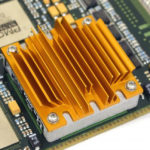
Thermal management can be as simple as the use of passive devices such as heat sinks or thermal spreaders and can optionally include circuitry to monitor the operating temperature and shut down the system in the case of an overtemperature condition. Or it can also include an active approach that delivers high-performance and/or variable cooling based on real-time changes in the system’s thermal conditions.
You can’t manage what you don’t measure
Thermal management begins with the measurement of temperature. Temperature measurement begins at the design stage with a thermal mapping of the system to identify hot spots and other areas of concern from a thermal standpoint. Thermal mapping is necessary to enable the design of the correct thermal management system for the specific operating environment, and it identifies areas that need to be monitored (measured) during system operation. The following are some of the devices used to monitor the thermal environment in electronic systems.
Thermistors
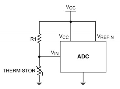
Thermistors are temperature-dependent resistors, usually made from conductive materials such as metal-oxide ceramics or polymers. The most common thermistors have a negative temperature coefficient (NTC) of resistance and are often referred to as NTCs. Positive temperature coefficient thermistors, known as PTCs, are also available but are not generally used in electronic systems. Characteristics of NTCs include operation up to +150°C, though some are capable of much higher temperatures, low-to-moderate cost (varying with accuracy), and reasonable linearity. Signal conditioning is required to use NTCs. A thermistor is often used together with a fixed-value resistor in a voltage divider with the output digitized using an analog-to-digital converter (ADC).
Resistance Temperature Detectors
Resistance temperature detectors (RTDs) are resistors whose resistance varies with temperature. Platinum is the most common and most accurate RTD material. Platinum RTDs are referred to as Pt-RTDs. Nickel, copper, and other metals may also be used to make RTDs. Platinum RTD characteristics include a wide temperature range (up to about 800°C), excellent accuracy and repeatability, reasonable linearity. Like thermistors, RTDs require signal conditioning in practical applications. Because of their accuracy, stability, and wide temperature range, platinum RTDs are used in various precision applications, including instruments, process control, and automotive systems.
Thermocouples
Thermocouples are made by joining two wires of dissimilar metals. The point of contact between the wires generates a voltage that is proportional to temperature. Characteristics include wide temperature range (up to +1800°C), low-cost (depending on the thermistor is packaged), very low output voltage (about 40µV per °C for a K type), reasonable linearity, and the need for moderately complex signal conditioning (cold-junction compensation and amplification).
Temperature Sensor ICs
Temperature sensor ICs take advantage of the thermal characteristics of silicon PN junctions. Because they are active circuits built using conventional semiconductor processes, they can take various forms and include a variety of features (such as digital interfaces, ADC inputs, and fan-control functions). The operating temperature range for temperature sensor ICs extends as low as -55°C and as high as +125°C, with a few devices operating to an upper limit of around +150°C.
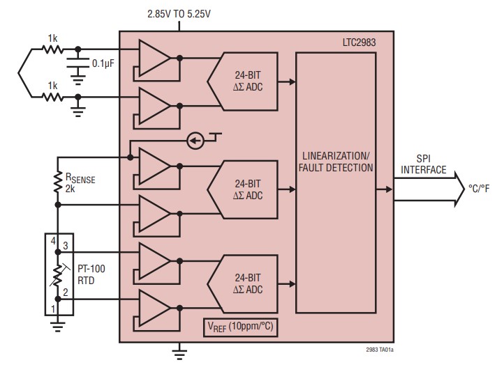
There are also high-performance digital temperature measurement ICs which directly digitize RTDs, thermocouples, thermistors, and external diodes with high accuracy and resolution. A high-performance analog front end combines low noise and low offset buffered ADCs with all the necessary excitation and control circuits for each sensor. Measurements are performed under the control of a digital engine combining all the algorithms and linearization as needed.
Analog temperature sensor ICs convert temperature to voltage or, in some cases, to current. The simplest analog temperature sensors have just three active connections: for ground, power supply voltage input, and output. Other analog sensors with enhanced features may have additional inputs or outputs—for example, comparator or voltage reference outputs.
Integrating an analog temperature sensor with an ADC is a simple way to create a temperature sensor with a direct digital interface. Such a device is normally called a digital temperature sensor or a local digital temperature sensor. “Local” refers to the fact that the sensor measures its own temperature instead of a remote sensor that measures the temperature of an external IC or discrete transistor. There is a wide variety of digital temperature sensors available with various feature sets.
Coefficient of thermal expansion
The coefficient of linear thermal expansion (CTE) is a material property that measures the extent to which a material expands upon heating. Different materials expand by different amounts. Over small temperature ranges, the thermal expansion of uniform linear objects is proportional to temperature change. Thermal expansion can be useful in applications such as bimetallic strips for the construction of thermometers. Still, it can generate detrimental internal stress in electronic assemblies that employ various materials such as copper and various substrates and/or encapsulants.
Typical electronic assemblies and thermal management systems use materials with different CTEs. Those different CTEs can cause significant mechanical stresses in the assembly and result in reduced reliability and failures. Understanding the CTEs of the various materials used in thermal management systems and electronics, in general, is critical to ensuring maximum reliability.
For example, matching the CTE as closely as possible to that of the substrate to be potted is crucial in potting electronic circuits. A significant mismatch can result in component damage due to the forces exerted as the encapsulant expands or contracts with temperature changes, possibly resulting in circuit failure.
CTE is also important when casting electrical components such as transformer bushings and transformer coils. Significantly mismatched coefficient of thermal expansion can result in cracking or insufficient adhesion to conductors. And matching CTEs of various components in power conversion circuits which experience high-temperature operation and wide temperature swings is critical.
This FAQ looked at the basics of thermal management, temperature measurement, and the importance of matching the CTEs of various system components. The remaining three FAQs in this series will dig into various methods and devices used to implement thermal management systems, including passive approaches employing heatsinks in part two, the use of fans and blowers to increase thermal transfer rates in part three, and the use of liquid cooling for high-performance systems in part four.
References
Robust system thermal management, Cypress Semiconductor
Thermal management handbook, Maxim Integrated
What is Coefficient of Thermal Expansion (CTE)? How Do I Measure It?, C-therm