Filters will allow some signals to pass through while blocking others. A bandpass (a.k.a. band-pass) filter allows signals of a certain frequency range (“a band of frequencies”) to pass through the filter as-is. (This range of accepted frequencies is called the passband. The size or range of the passband is called the bandwidth.) With a bandpass filter, anything higher or lower than the selected frequency range will be blocked (attenuated). This is useful for removing unwanted noise by blocking everything that you know you will not be using anyway. One example is with the audio frequency range for use with music and processing speech; the audio frequency range for these applications runs from about 20Hz to 20kHz.
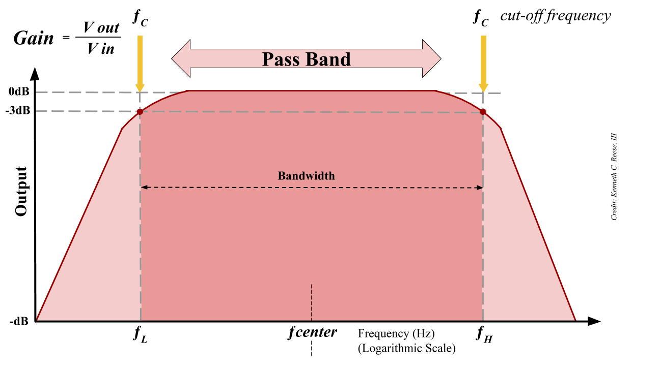
Figure 1: A bandpass filter with low cutoff frequency (fL), center frequency (fC), and high cutoff frequency (fH) shown in relationship to bandwidth and pass band.
Analog signals often need to be filtered before converting them to digital signals for processing. (Both analog and digital filters exist, but we are talking about analog filters, which remove noise before it’s digitized.) Removing noise at higher frequencies (above ~1MHz) can be accomplished with a circuit using passive components (capacitors (C), resistors(R), and inductors(L).) At lower frequencies (1Hz to 1MHz) the inductor can get physically large and uneconomical, so an active filter can be used to perform much like the LRC filter but at a lower frequency. An active filter uses an active component like an operational amplifier, as well as passive components.
The three most well-known ways to filter are low pass, high pass, and bandpass. Two less well-known categories exist, and these are the band-rejection (notch) filter (a kind of inverse bandpass filter) and all-pass filters (which shift phase). A low-pass filter allows only signals at low frequencies through. A high pass filter allows only signals at higher frequencies to pass through. (A simple way to create a bandpass filter is to place a low pass and high pass filter in series.) Some specifications of concern with a bandpass filter are the cutoff frequencies. The low cutoff frequency (fL) specifies the low end of the band pass filter where signals, beginning with the low cutoff frequency, are allowed to pass through the filter. The high cutoff frequency (fH) specifies the highest frequency that the band pass filter will allow to pass through.
Another specification of concern is the gain at the center frequency (fC) and the quality factor (Q) of the bandpass filter, which has to do with the selectiveness of the filter. A bandpass filter with a high Q factor represents a bandpass filter with a narrow pass band; that is, a high Q factor means fewer signals of unwanted frequencies will pass through. A low Q factor means that the pass band is wide, and therefore allows a wider range of frequencies to pass through the filter. Generally, the cutoff frequency is the frequency where the amplitude of the filter is 3dB less than the pass band’s amplitude.[i]
In reality, band pass filters may not completely block unwanted signals. Signals that are not in the pass band may simply be attenuated, or reduced significantly in amplitude. Signals that are in the passband will be amplified by the gain associated with fC. An ideal filter would look like a step function; allowing frequencies at precisely fL to pass through the filter circuit and abruptly stopping throughput at precisely fH. As it stands, the problem is that the filter does not completely attenuate everything and is gradually worse at allowing signals leading up to the cut-off frequency fL, and gradually gets better at attenuating signals as we move away from the high cut-off frequency, fH. This imperfect exclusion is called “roll off.” The roll off can be seen in the curve leading up to the plateau in figure 1 and again in the curve falling away from fH. Higher order filters (second order, third order, etc.) will have a sharper roll-off rate. Higher order filters have more components.
For more information on active filters, there’s an excellent resource online called Active Filters by Analog Devices.
[i] https://wiki.analog.com/university/courses/tutorials/index
The post Basics of bandpass filters appeared first on Analog IC Tips.