When two waves – sound, electrical, in water – that are of different frequencies are conveyed in the same medium, the alternating constructive and destructive interference gives rise to sum and difference frequencies. If acoustic tones are close to the same frequency, the resultant difference signal will be heard as a distinctive beating sound that becomes at once louder and slower as the two tones become closer in frequency. The additive resultant that is the sum of the two frequencies is often outside the audible range.
This additive phenomenon is known as the heterodyne effect, and it is useful in various electronic applications. The best known of these is the superheterodyne, which was invented during World War I and has remained the dominant type of radio reception to this day. Here a received RF signal is mixed with a locally synthesized frequency to produce a lower intermediate frequency (IF) carrier. The IF carrier is useful because it is still modulated by the audio signal. Because the IF is a uniform lower frequency for the entire RF band, it can be more efficiently amplified, making for enhanced sensitivity and selectivity.
 Heterodyning is used in other applications, including the modern oscilloscope where high-frequency signals that would otherwise be beyond the reach of the instrument are converted down to a usable level. Another example is the theremin, an electronic musical instrument. Heterodyning produces a varying audible pitch in response to movement of the musician’s hands, which are capacitively coupled to the instrument.

An analog mixer as might be found in a simple transistor radio. The local oscillator doubles as an amplifier.
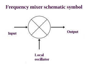
For heterodyning to take place, there has to be a (generally solid-state) frequency mixer. This device in its most common form has two inputs. One is the signal to be processed and the other is connected to a local oscillator. The output is the difference between the two inputs. Frequency mixers are also used at the transmitter to modulate the fixed-frequency carrier.
Mixers can be passive, composed of diodes, where the nonlinear relation between current and voltage performs the desired function. In an active frequency mixer, amplification is provided in addition to frequency conversion. The output is at a higher power level than the input, but downsides can be instability, noise and greater power consumption.
Other mixer functions, besides frequency shifting, are modulator, phase detector and frequency multiplier. Radio receivers usually incorporate separate mixer stages to create an intermediate frequency and to operate as a detector for signal demodulation.
Most mixers used in instrumentation are balanced mixers. Mixers that are unbalanced pass significant levels of the local oscillator and RF signals through to the output. Balanced mixers, on the other hand, block both the IF and RF inputs.
There are different varieties of balanced mixers. Single-balanced mixers will suppress either the LO or RF signal but not both. Double-balanced mixers suppress both input signals.
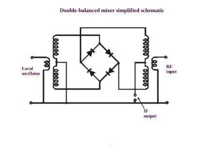
The four diodes used in double-balanced diode mixers are generally all fabbed on the same chip in the interest of closely matched their performance parameters. In its simplest form the double-balanced diode mixer consists of two unbalanced-to-balanced transformers and a diode ring.
Double-balanced mixers frequently employ electronic switches in a bridge formation. The switches (typically diodes or FETs) reverse the input RF signal under the action of the local oscillator functioning as a square-wave switching signal. They generally work better than analog mixers in terms of better dynamic range and less noise.
One key aspect of a double-balanced mixer is whether any of the LO or RF signals appear at its IF output. The degree to which this happens depends upon the diode/switch and transformer uniformity. Consequently, the quad diodes (or switching transistors) used in these mixers are generally all on the same chip. This gives them closely matched performance parameters, particularly with regard to giving all the diodes virtually the same forward voltage. Additionally, the balanced diode switching precludes direct connection between the circuit’s two transformers so the topology offers high isolation between the RF and IF inputs.
The transformers are also critical components because they have to handle a relatively wide band of frequencies. And properties of the transformers in the individual legs must match closely to balance the RF mixer.
In operation, the local oscillator signal turns on first one arm and then the other within the diode ring. The points where the local oscillator enters the diode ring at the junction of two diodes appear as a virtual earth to the RF signal. This means the points where the RF signal enters are alternatively connected to ground as the diodes turn on and off. Thus the RF signal with alternating inverse phases is routed to the IF output according to the switching action of the local oscillator. Effectively, the signal at the IF output has been multiplied by the local oscillator waveform.
It is also possible to design double-balanced mixers that use FETs instead of diodes. These tend to handle high-level signals well and offer highly linear performance.
The post Basics of frequency mixing and mixers appeared first on Test & Measurement Tips.
