by Miles Budimir, Senior Editor
Testing electric motors doesn’t have to be a mystery. Knowledge of the basics together with powerful new test equipment vastly simplifies the job.
Electric motors have had a reputation for being a mix of science and magic. So when a motor fails to operate it may not be obvious what the problem is. Knowing some basic methods and techniques along with having a few test instruments handy helps detect and diagnose problems with ease.
When an electric motor fails to start, runs intermittently or hot, or continually trips its overcurrent device, there my be a variety of causes. Sometimes the trouble lies within the power supply, including branch circuit conductors or a motor controller. Another possibility is that the driven load is jammed, binding or mismatched. If the motor itself has developed a fault, the fault may be a burnt wire or connection, a winding failure including insulation deterioration, or a deteriorating bearing.
A number of diagnostic tools, such as clamp-on ammeters, temperature sensors, a Megger or oscilloscope, can help illuminate the problem. Preliminary tests generally are done using the ubiquitous multimeter. This tester is capable of providing diagnostic information for all kinds of motors.
Electrical measurements
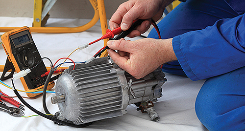
If the motor is completely unresponsive, no ac humming or false starts, take a voltage reading at the motor terminals. If there is no voltage or reduced voltage, work back upstream. Take readings at accessible points including disconnects, the motor controller, any fuses or junction boxes, and so on, back to the over-current device output at the entrance panel. What you’re looking for is essentially the same voltage level as measured at the entrance panel main breaker.
When there is no electrical load, the same voltage should appear at both ends of the branch circuit conductors. When the circuit electrical load is close to the circuit capacity, the voltage drop should not exceed 3% for optimum motor efficiency. In a three-phase hookup, all legs should have substantially equal voltage readings, with no dropped phase. If these readings vary by a few volts, it may be possible to equalize them by rolling the connections, taking care not to reverse rotation. The idea is to match supply voltages and load impedances so as to balance the three legs.
If the electrical supply checks out, examine the motor itself. If possible, disengage the load. This may restore motor operation. With power disconnected and locked out, attempt to turn the motor by hand. In all but the largest motors the shaft should turn freely. If not, there is an obstruction inside or a seized bearing. Fairly new bearings are prone to seizure because the tolerances are tighter. This is especially true if there is ambient moisture or the motor has been unused for a while. Often good operation can be restored by oiling front and rear bearings without disassembling the motor.
If the shaft turns freely, set the multimeter to its ohms function to check resistance. The windings (all three in a three-phase motor) should read low but not zero ohms. The smaller the motor, the higher this reading will be, but it should not be open. It will usually be low enough (under 30 Ω) for the audible continuity indicator to sound.
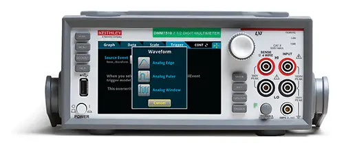
A DMM (digital multimeter), such as this Keithley DMM7510 from Tektronix, is a must-have instrument for motor testing. A wide range of DMMs are available to measure voltage, current, and resistance, depending on the motor power ratings.
Small universal motors, such as those used in portable electric drills, can contain extensive circuitry including a switch and brushes. In the ohmmeter mode, connect the meter to the plug and monitor the resistance as you wiggle the cord where it enters the enclosure. Move the switch from side to side and, with a trigger switch taped so it remains on, press on the brushes and turn the commutator by hand. Any fluctuation in the digital readout may point to a defect. Often a new set of brushes is what’s needed to restore operation.
Amperage or current readings are useful in motor testing as well. With a voltage reading, you know the electrical energy available at the terminals, but you don’t know how much current flows. Multimeters always have a current function, but there are two problems with it. One is that the circuit under investigation must be cut open (and later restored) to put the instrument in series with the load. The other difficulty is that the typical multimeter is not capable of handling the amount of current present in even a small motor. All the current would have to flow through the meter, burning the probe leads if not destroying the entire instrument.
An essential tool for motor current measurement is the clamp-on ammeter. It circumvents such difficulties by measuring the magnetic field associated with the current, displaying the result in a digital or analog readout calibrated in amperes.

Multifunction instruments, such as this CM174 clamp meter from FLIR, give test engineers the power of multiple instrument functions in one unit. The CM174 features Infrared Guided Measurement (IGM technology powered by an integrated FLIR Lepton thermal imaging sensor, giving users extra visual data to help in troubleshooting.
Clamp-on ammeters are user friendly. Just open the spring-loaded jaws, insert either the hot or neutral conductor, then release the jaws. The wire need not be centered in the opening and it’s OK if it passes through at an angle. However, an entire cable containing hot and neutral conductors cannot be measured this way. That’s because the current flowing through the two wires travels in opposite directions so the two magnetic fields cancel out. Consequently, it’s not possible to measure the current in a power cord, as is often desired. The use of a splitter fixes the problem. This is a short extension cord of adequate rating with about six inches of jacket removed so that one of the conductors can be separated and measured.
Digital and legacy analog clamp-on ammeters work well and are capable of measuring up to 200 A, which is adequate for most motor work.
The basic procedure is to measure the start-up and running current for any motor while it’s connected to a load. Compare the reading to documented or nameplate specifications. As motors age, the current drawn generally rises because winding insulation resistance drops. Excess current causes heat, which must be dissipated. Insulation degradation accelerates until there’s an avalanche event, causing motor burn out.
The clamp-on ammeter reading will tell you where you stand on this continuum. In an industrial facility, as part of routine motor maintenance, periodic current readings can be taken and put into a log posted nearby so damaging trends can be spotted in advance to avoid expensive downtime.
Insulation testing
The insulation resistance tester (or megohmmeter), generally known by its trade name Megger, can provide critical information regarding the condition of motor insulation. In an industrial facility, the recommended procedure is to perform periodic tests and record the results so damaging trends can be detected and corrected to prevent an outage and extensive downtime.
The insulation resistance tester resembles a conventional ohmmeter. But rather than the typical three-volt test voltage derived from an internal battery and present at the probes, the Megger provides a much higher voltage applied for a proscribed length of time. The leakage current through insulation, expressed as resistance, is displayed so it can be graphed. This test may take place on installed or on-the-reel cable, tools, appliances, transformers, power distribution subsystems, capacitors, motors and any type of electrical equipment or wiring.
The test may be non-destructive, for in-service equipment, or prolonged at elevated voltage to test prototypes to the point of destruction. A bit of a learning curve is involved in using the Megger. The correct settings, connection procedures, test durations and safety precautions must be implemented to avoid damaging the equipment or electrocuting the operator or coworkers.
The motor under test must be powered down and disconnected from all equipment and wiring that’s not to be included in the test. Besides invalidating the test, such extraneous equipment could be damaged by the applied voltage. Additionally, unsuspecting individuals could be exposed to hazardous high voltages.
All wiring and equipment has an inherent amount of capacitance, which is generally significant in large motors. Because the equipment is in effect a storage capacitor, it’s essential that lingering electrical energy be discharged before and after each test. To do this, shunt the relevant conductor(s) to ground and to each other before reconnecting the power source. The unit should be discharged at least four times as long as the test voltage was applied.
The Megger is capable of applying different voltages, and the level should be coordinated with the type of equipment under test and the scope of the inquiry. The test generally applies between 100 and 5,000 V or more. A protocol involving voltage level, time duration, intervals between tests and connection methods must be composed, taking into account the type and size of the equipment, its value and role in the production process and other factors.
Motor testing equipment
Newer more contemporary instruments make testing even easier. For instance, test equipment such as Fluke’s 438-II Power Quality and Motor Analyzer uses algorithms to analyze not only three-phase power quality but also torque, efficiency and speed to determine system performance and detect overloaded conditions, eliminating the need for motor load sensors.

Using proprietary algorithms, the 438-II from Fluke measures the three-phase current and voltage waveforms and compares them against rated specifications to calculate motor mechanical performance.
It provides analysis data for both the electrical and mechanical characteristics of the motor while in operation. Using proprietary algorithms, the 438-II measures the three-phase current and voltage waveforms and compares them against rated specifications to calculate motor mechanical performance. The analysis is presented in simple readouts, making it easy to gauge the operating performance and determine if adjustments are needed before failures cause an operational shut down.
The analyzer also provides measurements to determine a motor’s efficiency (for example, the conversion of electrical energy to mechanical torque) and mechanical power under operating load conditions. These measures allow for determining the motor’s in-service operating power compared to its rated power to see if the motor is operating in overloaded condition or, conversely, if it’s oversized for the application, energy may be wasted and operating cost increased.
Other developments include integrating multiple instrument functions into one unit. For instance, a new thermal imaging clamp-on ammeter from FLIR has a built-in infrared camera, which gives the user a visual indication of temperature differences and thermal anomalies.
FLIR
www.flir.com
Fluke
www.fluke.com
Keithley/Tektronix
www.tek.com/keithley
The post The basics of motor testing appeared first on Test & Measurement Tips.
