Understanding the role and implications of impedance in RF transmission lines and antennas is vital to successful system performance.
In any design requiring the transfer of an RF signal and its energy from one functional block or component in a system to a subsequent one in the signal chain, there’s almost always the issue of impedance matching. In addition, there is also the closely associated topic of VSWR as related to transmission lines and antennas (don’t worry: VSWR is defined and discussed in detail below). This FAQ looks at multiple aspects of these two intertwined topics: the underlying issues, making measurements, and implementing matching solutions.
Q: What is the impedance-matching problem and its answer?
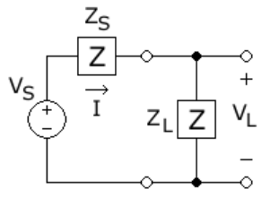
A: In RF circuits (and low-frequency and even DC ones), an important objective is to pass the RF power along the signal chain. Thevenin circuit analysis shows that maximum power is transferred when the impedance of the source and the load’s impedance are complex conjugates of each other. (You can see proofs of this perhaps non-intuitive situation in References 1 and 2). Mathematically, maximum power transfer is obtained when the source’s output impedance (ZS=Rs+jXs) is equal to the complex conjugate of the input impedance of the load (Zl=RL-jXL). This is called conjugate matching.
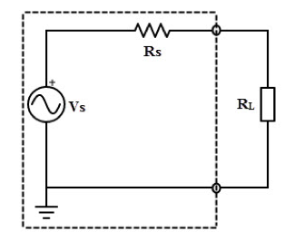
For purely resistive situations, this simply means that the source and load impedances should have the same value (Figure 1). But for non-resistive loads with reactive aspects, things are more complicated: a capacitive source needs an inductive load, and vice versa (Figure 2).
Q: Why are impedance issues more complicated for RF circuits than for lower-frequency and even DC systems?
A: The reason is that impedance is a function of frequency. For lower-frequency and DC regions, the reactive component of the impedance is often quite small and negligible; the unavoidable stray and parasitic capacitances and inductances are usually insignificant there but cannot be ignored in the megahertz and gigahertz ranges. In the audio range (20 Hz to 20 kHz), the output impedance of an amplifier should be matched to a loudspeaker impedance to provide maximum power transfer and thus the maximum volume of sound. Lower-frequency reactive values can be an issue; however, even a 50/60 Hz motor has considerable inductance in its windings, affecting power transfer and driver characteristics when driving the motor.
Q: Are impedance issues solely related to electronics?
A: No, it is important whenever a system needs to transfer energy, such as ultrasound energy from an acoustic emitter to skin and then into the body, or sense the reflected ultrasound energy. Again, this article focuses on impedance and related issues only in the higher-frequency electromagnetic spectrum.
Q: What does “matched” source and load impedance mean?
A: Maximizing this power transfer is an important design priority. When engineers say their impedances are “matched” it does not mean they are equal. “Matched” is the standard but perhaps confusing term in that sense. It’s important to keep in mind that “matched” means the impedances are complex conjugates of each other, not equal. Of course, for resistive-only source and load impedances, they are equal.
Q: How much power can ideally be transferred under matched conditions?
A: The math and analysis show that the maximum is 50%.
Q: Are maximum power transfer and maximum efficiency the same?
A: No, but they are often confused. Efficiency is the percentage of input power that is dissipated in the load. If the load resistance is increased, higher efficiency can be achieved. In contrast, the maximum power transfer theorem defines the load resistance, which will get maximum magnitude of power delivered to it by the source. However, input power from the source depends on load; if the load resistance is increased, overall power decreases in magnitude, but the percentage of input power transferred to load increases.
In other words, as load resistance increases, more power is dissipated in the load than in the source impedance, and so efficiency is increased. The magnitude of overall power is decreased, however, due to the increased resistance. Similarly, if the load resistance is decreased, a lower percentage of total input power is dissipated in the load, and efficiency decreases. In most RF designs, maximum power transfer is the primary concern.
The next part of this article looks at nominal impedance and VSWR.
Related EE World Content
What are the functions and principles of S-parameters (Part 1)?
What are the applications and measurements of S-parameters? (Part 2)
RF power amplifier, Part 1: Functions and Elements
Solar cells and power, Part 2 – power extraction
Measuring antenna properties
Using the Smith chart for Impedance matching, Part 1
Impedance matching and the Smith Chart, Part 2
The difference between SWR and TDR meters
Measure power in complex RF signals
What are RF waveguides? Part 1: context and principles
What are RF waveguides? Part 2: implementation and components
References
- Wikipedia, “Maximum power transfer theory”
- Tutorials Point, “Maximum Power Transfer Theorem”
- Microwaves 101, “Why Fifty Ohms?”
- Belden, “50 Ohms: The Forgotten Impedance”
- High Frequency Electronics, “There’s Nothing Magic About 50 Ohms”
- Wilson Amplifiers, “50 Ohm vs. 75 Ohm: Which is Best For You?”
- Wikipedia, “Standing wave ratio”
- Antenna-Theory, “VSWR (Voltage Standing Wave Ratio)”
- Electronics Notes, “What is VSWR: Voltage Standing Wave Ratio”
- Electronics Notes, “How to Measure VSWR: approaches & test instruments”
- Maxim Integrated Products, “Glossary Definition for impedance-matching”
- Maxim Integrated Products, “Glossary Definition for VSWR”
- Nuts and Volts, “Impedance Matching”
- Mini-Circuits, “Impedance Matching Devices”
- Mini-Circuits, “Demystifying Transformers: Baluns and Ununs”
- NI (National Instruments), “Impedance and Impedance Matching”
- Tektronix, “Introduction to VNA Basics”
- Triad Magnetics. “Understanding the Maximum Power Theorem”
- QSL Net, “50 MHz (6 Meter) Tuner Circuits”
- QSL Net, “Six Meter Transmatch (Tuner)”
- M0UKD (Amateur Radio Personal Site), “End Fed Half Wave Antenna Coupler (EFHW)”
- Altium Limited, “Stripline vs Microstrip: PCB Routing Differences and Guidelines”
- Researchgate, “A Self-Complementary 1.2 to 40 GHz Spiral Antenna with Impedance Matching”