The classic wooden breadboard is obsolete, but its name refers to a vital engineering tool that has changed to meet today’s component and design realities.
Wooden breadboards are obsolete as platforms for circuits using modern components, of course, and so-called solderless breadboards are also of very limited usefulness. At the same time, the way designers approach system development has dramatically changed as well.
How so? In many cases, the project development process has gone from adding one new block at a time and seeing the impact of that next piece, then adding another, and so on. Instead, we now have an “all-up” strategy.
In all, every subcircuit or function is independently tested as much as possible or practical, then all the pieces ate put together in their final configuration for test and evaluation. This approach recognizes that adding one block or function at a time is often misleading. The reason is that the complex interactions of the various blocks and functions only really become apparent when they are all connected. In fact, even the incremental setup and test plan used when adding one block at a time are often very different and even misleading compared to the one used for the all-up test.
All-up is not a new concept. It was used by Admiral Rickover when he led the radical and innovative design for the Nautilus, the first nuclear submarine. The Apollo moon-landing project also formalized it, when all the stages of the Saturn rocket, including the third stage with the lunar module and lander, were assembled together for total-configuration evaluation; rather than add the second stage to the first and test, add a stage and test again, then add the lunar module and test yet again, and so o..
Obviously, most engineers are not working on projects of such scale, but they are working on projects with many disparate functions. The small-scale analogy would be to individually design, build, and test each function or module to the maximum possible extent, such as the power-supply subsystem, the analog-sensor front end, the RF-link module, and the supervisory microcontroller, for example. The input/output interface of each sub-circuit (physical, format, protocol) must be defined and carefully tested.
In addition, many projects use purchased, complete units such as Arduino boards and RF modules, as major functional elements. There’s no need to re-test the internal functionality of these. The point of using these “canned” modules is to minimize that part of the design evaluation, and instead focus on their connectivity and interaction with the other subfunctions or modules. In other words, it’s largely about system integration of the various functional blocks more than signal-path and flow within and through the blocks.
Breadboard options for this reality
There are two aspects to breadboarding this situation. One is to build a working subcircuit or module as an independent unit; the other is to connect them all in the target arrangement physically.
While designers can build their own circuits and boards for the former, it’s a lot of work and risk in time, money, and frustration. Instead, today’s alternative is to use vendor-supplied evaluation boards and reference design as much as possible. These are small, proven circuit boards with a tested layout and arrangement of the core device(s) and all associated support components. They are especially beneficial for sensitive or higher-speed circuits where issues of layout, choice, placement of support components and passives, and other subtleties have a major impact on the performance of the core IC.
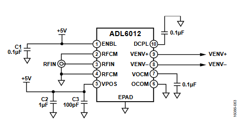
Consider a “small” IC such as the Analog Devices ADL6012, a 2-to-67 GHz, 500-MHz bandwidth broadband envelope detector. The basic interconnection of this 10-lead LFCSP looks fairly simple on its schematic diagra. Still, actuall use is more difficult as it requires a careful layout, bypassing, and high-end RF connectors (Figure 1).
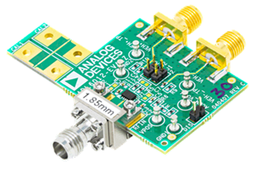
Designers looking to incorporate this RF IC into their design make sense first to understand its characteristics, test its interfaces, and “fine-tune” its fit in the overall by leveraging the ADL6012-EVALZ evaluation board (Figure 2). This would be done at the breadboard stage prior to creating a final schematic and working out the layout and packaging.
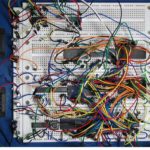
The breadboard challenge is to physically enable the use of the evaluation board, add power supplies, and provide the RF input amplifier and specified differential output load. To this must be added any processor and interfaces which must be exercised and debugged (both hardware and software). Doing so requires a combination of breadboarding techniques, platforms, and approaches.
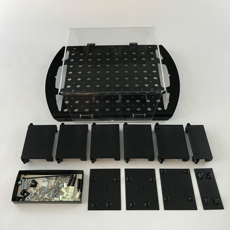
Addressing this situation are innovative breadboarding systems such as the Phase Dock 10104 Mounting Prototyping System (Figure 3); there are other systems from other sources such as Schmartboard, Inc. A core system consists of a 10 × 7-inch base matrix with 54 square inches of work surface, five “Clicks” in two sizes used to mount electronics, as well as “Slides” used to mount Arduino, Raspberry Pi, or similar modules. It also includes the small hardware items such as screws which enable the engineer to assemble the Click/Slide combos, mount electronics on the Slides, mount electronics directly to the Clicks (without Slides), add higher-profile “tower” electronics, and manage wires and cables. There’s also an optional clear plastic cover which provides protection, enhances appearance, and facilitates transport.
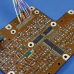
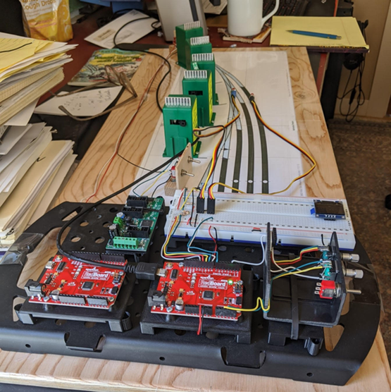
This product-development system allows for mixing, on a single platform, of different breadboard and module technologies, such as solderless breadboards, specialty boards with screw terminals and connectors, and even brackets holding discrete switches and potentiometers (Figure 4). They are all mounted firmly to the Phase Dock base and then connected as needed to test the system concept and debug it with needed access to key signals and test points.
Not only does it support various modes of breadboarding including the solderless board, but it also provides a clean appearance which (I can tell you from personal experience) is important when presenting your ideas and project to a teacher, judges, and even to management or outside investors. It allows you to mount and protect pre-made modules (again, perhaps as an Arduino board) onto a base-plate matrix, then add additional areas for your own circuitry, including sensors, relays, I/O, displays, LEDs, rotary encoders, and all sorts of peripheral hardware that is needed to really build, test, and explain the project.
The venerable breadboard which gave its name to our modern approaches, is no longer a viable option. New breadboard technologies and approaches were devised for the new world of discrete transistors, passive components, and DIP ICs but these, too, have faded back with the introduction of ultra-small, ultradense ICs, almost-invisible passive components, and complete canned modules.
EE World Related content
Mounting base kit simplifies electronic prototyping tasks
Understanding delay for I/O: Using Arduino functions vs. coding the MCU
Plug-And-Play Diagnostic Devices
Considerations in PCB layout guidelines
Getting started in electronics: core components
What is a Board Support Package?
A “canned” module/IC solution simplifies wireless implementation, but potential design-in issues remain
External references
Wikipedia, “Fahnestock clips”
Schmartboard Breadboard Systems
Phase Dock Inc., Universal WorkBench system