My current oscilloscope is a four-channel, high-speed, deep memory instrument which is still good for analog work in spite of its age. Newer analog oscilloscopes often have mixed signal options with eight or more digital channels. Even for an analog engineer, these can be useful as you can often be working with ADCs, DACs or other analog-digital devices. In the past, I could decode the odd byte or two of RS232 data manually on the oscilloscope but with SPI and multi-byte I≤C communications more common it has become rather tricky. The incremental cost of adding some digital inputs to a new oscilloscope purchase is not that high — a Keysight Technologies DSOX3054T is $11,670 and the MSOX version with 16 digital inputs is $13,166, so $,1496 extra. However, it is a high cost if you already have a 500MHz, 4-channel deep memory oscilloscope and don’t need to replace it.
My search for a solution ended up at Tech Tools. Tech Tools make the DigiView PC-based logic analyzers and, while I am not usually a fan of PC-based instruments (I prefer stand alone devices), in this case, it seemed like the perfect solution and would save over $10,000. Prices are $479 for the DV509 9-channel unit up to $999 for the DV3500 — a 36-channel unit.
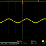
The latest versions have USB 3.0 interfaces and the 9- and 18-channel ones are USB powered. They are tiny, although that is not much of a consideration for me, but better than it being huge. I think the main benefits of the unit are actually the features of the included software, without which the DigiView unit wouldn’t do much anyway. The features seem to be designed by someone who has actually used the device which isn’t always the case with equipment. For example, I needed to check a two channel ADC with SPI interface was working, and the software will not only allow you to display the data as an analog signal but it will let you select alternate bytes so the two channels of ADC data are not mixed up.
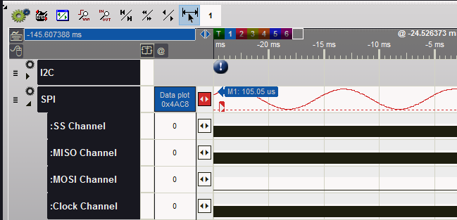
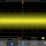
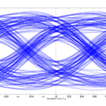
The screen capture above shows the data from one channel of the dual channel SPI ADC. One ADC channel is being fed with a sine wave and the sine wave shown above is from the decoded SPI data. The other ADC channel was not connected. Without the ability to select alternate SPI words (the ADC was 16 bit), the output would look like this:
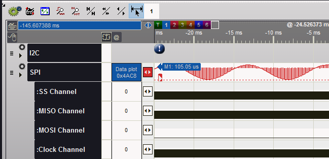
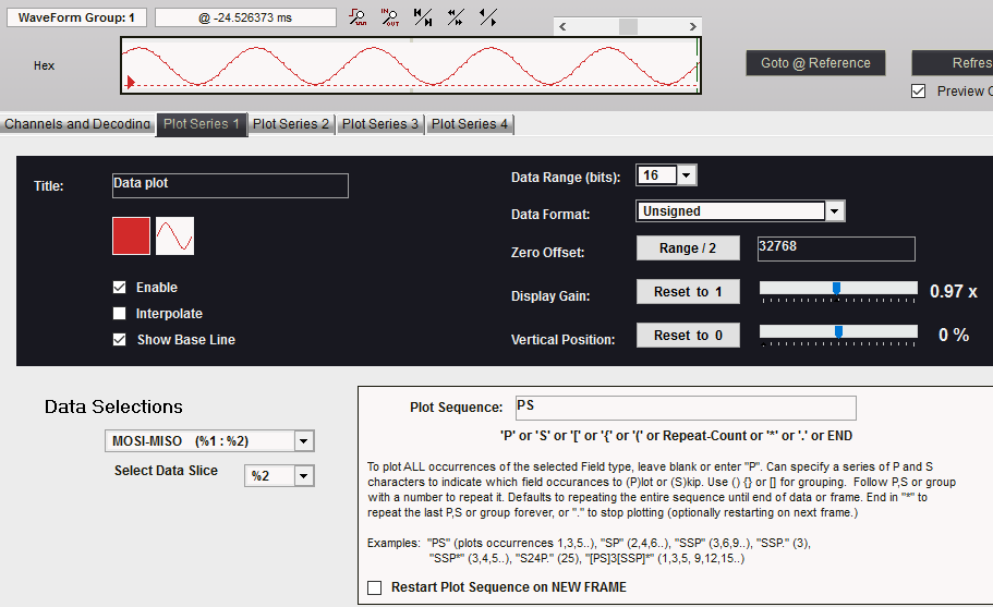
Now the analog plot of the SPI shows the data alternating between the two channels. The settings available in the software are quite comprehensive and include the ability to plot multiple signals on the same plot from different words in the sequence as well as scaling options.
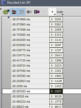
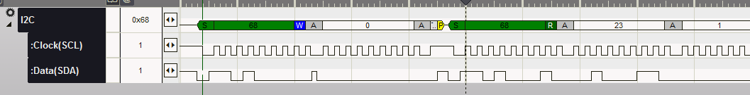
You can, of course, look at the raw data if you like, and select the radix.
You can obviously decode parallel data as well. This just only scratches the surface of the things you can do such as CAN bus, I≤C and asynchronous protocol decode.
The data collection can be over a very long time because it only collects data when there is a transition – it doesn’t record lots of zeros at the maximum sample rate. So, you are limited by the number of transitions rather than time. I would hope that mixed signal oscilloscopes would do the same, although old logic analyzers didn’t.
One other problem with my old oscilloscope was the ZIP drive used for saving screen captures. Screen captures are very useful for a hard record to show problems, features or performance and for including in reports, manuals or other documents. ZIP drives have been obsolete for a long time and so I needed a solution. As the oscilloscope has a VGA output which duplicates the image on the TFT display, the solution was simple – the Epiphan VGA2USB interface https://www.epiphan.com/. That has now been replaced by the DVI2USB 3.0. It isn’t cheap and does do far more than I need, but like the Tech Tools Digiview it will give me a number of years use out of old equipment that still has the performance I need, and would otherwise be expensive to replace.

Leave a Reply
You must be logged in to post a comment.