Among the problems circuit designers have to contend with in their fast and complex electronic environment are race conditions.
The term used to be exclusively applied to electronic logic problems but has now been adopted by software engineers working on multithreaded programs. Briefly, software race conditions arise in multithreaded software when multiple threads attempt to modify a piece of shared data simultaneously. Serious problems arise if the output of one thread affects another thread’s execution in a way that causes unexpected or incorrect results.
But in electronics, a race condition arises when a logic gate combines signals that traveled via different, unequal paths from a single source. In response to changes in the source signal, the inputs at the gates will change at different times.
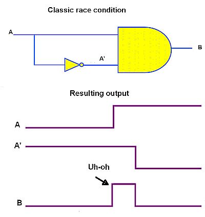 The classic example of a race condition is that of a two-input AND gate that receives logic signal A at one input and NOT A at the other as produced by an inverter. Theoretically, the AND gate output will always be 0. However, the signal passing through inverter will have some delay. If the signal through inverter reaches the AND gate later than the one without inverter, there will be a glitch. The result can be a system that exists in an undefined state.
The key to avoiding race conditions in digital designs is to ensure setup-and-hold criteria are met for each logic gate. The usual place where potential race problems can arise is in systems having multiple clocks. Different clock domains that are not properly synchronized can easily cause metastability events.
The typical way of dealing with multiple clocks is through a digital circuit called a synchronizer. This circuit converts a signal from a different clock domain into the recipient clock domain. That said, synchronizers don’t totally guarantee prevention of metastability. They only reduce the chances of it.
 The simplest synchronizer consists of two or more flip-flops in chain working on the destination clock domain. This approach allows for an entire clock period for the first flop to resolve metastability.
The input to the first stage is asynchronous to the destination clock. So, the output of first stage might occasionally go metastable. However, as long as metastability is resolved before next clock edge, the output of second stage should have valid logic levels. Thus, the asynchronous signal is synchronized with a maximum latency of two clock cycles.
Theoretically, it is still possible for the output of the first stage to be unresolved before it is sampled by the second stage. In that case, the output of second stage will also go metastable. Then a three-stage synchronizer is used if the probability of a metastable second stage is high.
Synchronizer schemes grow more complicated when there are multiple lines requiring synchronization. For example, handshaking-based synchronization controls the transfer of data via a handshaking protocol wherein source domain places data on a ‘REQ’ signal line. When it goes high, receiver knows data is stable on the bus and it is safe to sample it. After sampling, the receiver asserts an ‘ACK’ signal. This signal is synchronized to the source domain and informs the sender that data has been sampled successfully and that it’s safe to send new data. The problem with handshaking-based synchronizers is it takes many cycles to exchange handshaking signals. But it works well when the response time of one or both circuits is unpredictable.
The designer has various available tools to find race problems. One such is the Karnaugh map, wherein Boolean results are transferred from a truth table onto a two-dimensional grid in which the cells are ordered in Gray code. Race conditions are evident.
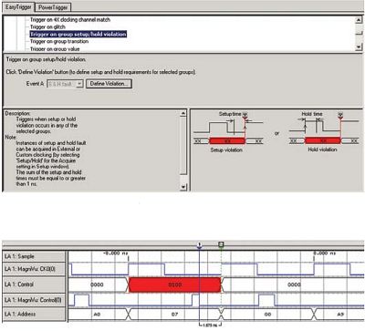
Because inadequate setup/hold margin is a common source of intermittent problems, modern logic analyzers have capabilities oriented toward noodling out these issues. It an be time consuming to search for setup/hold violations with a scope. The typical approach is to probe a clock and individual data lines. Modern logic analyzers can automate the search by triggering on and displaying any user-defined setup/hold violation on all signals simultaneously.
It is common to find logic analyzers with special setup-and-hold triggering modes. A point to note in using this feature is that logic analyzers have two ways to clock target signals: asynchronous mode and synchronous mode. In the asynchronous mode, also called timing mode, the logic analyzer samples the signals of the DUT using its internal clock. It is the synchronous mode, also called state mode, that is used for setup-and-hold triggering. To capture setup-and-hold violations, a comparison between the waveform edge timing relationship of the clock and target signals must be made. Here the logic analyzer samples acquired signals according using an external clock which is typically synchronized with DUT signals. In this mode, waveform states are only visible when they are valid.