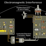
I recently came across an interesting article by Analog Devices in their February “Analog Dialogue” called “Ferrite Beads Demystified”. It was interesting beyond its analysis of ferrite beads because it covered one of the issues I have seen in the past with regards to power supply filtering — that of resonance between a power supply capacitor and a filtering inductor. I haven’t seen it discussed elsewhere although I am sure there must be other references to the problem. The problem you might face is that you want to clean up a switching regulator output going to other circuitry or reduce interference from a switching regulator going back into a power source or wiring (for EMC reasons). Simply adding some inductance seems like a good idea but it isn’t that straightforward. For example, consider a 1uH inductor with an 80MHz SRF (self-resonant frequency). This could typically be modeled as shown below.
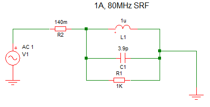
A ferrite bead would be similar in characteristics and the impedance of the inductor/ferrite bead would be:

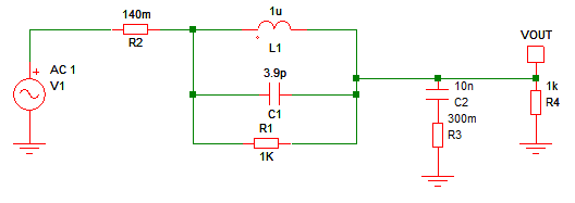
That all looks fine and would work well with a resistive load, but when you put it in series with a real circuit with some load capacitance, such as 10nF with 0.3 ohms ESR (equivalent series resistance) the problems start to show.
Now if you look at VOUT in an AC analysis you see this:
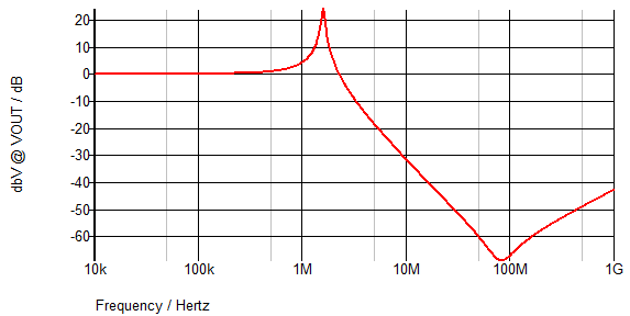
So, while you have good attenuation around 80MHz due to the inductor/ferrite bead, you now have a peak at 1.6MHz due to the resonant circuit created by the 1uH and 10nF. The response to a step input also shows the problem.
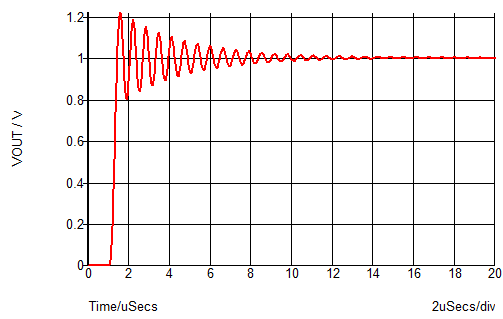
As your switching regulator is likely to be working at a lot lower frequency than 80MHz (although harmonics of the switching frequency may be important for EMC) you could be making your power supply quality considerably worse by adding the filtering. Also, the unstable transient response will most definitely not be what you were wanting.
Three methods of fixing the problem are suggested in the Analog Dialogue although the first – adding a series resistance to the decoupling capacitor – is not very realistic. If the capacitor is on the output of a switching regulator then it will actually consist of the sum of any decoupling capacitors in your circuit. If it is on the input to the switching regulator (where the ferrite bead could be used to prevent EMC issues back down the power source) then the switching regulator will most likely want a good quality decoupling capacitor – probably 10uF or more.
You could increase the inductance or capacitance but that will only move the problem around and not fix it. Adding a damping resistor across the inductor does reduce the peak, at the expense of the higher frequency attenuation. Quite a low value resistor is needed. This shows a comparison with 5 ohms in parallel with the inductor (green trace).
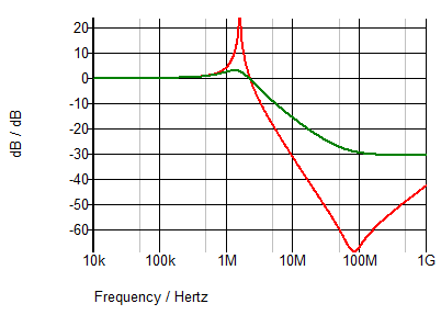
The peak at 1.6MHz has been reduced considerably but at the expense of the higher frequency attenuation. In fact, the result is almost the same as simply using the resistor and no inductor. The benefit would be the voltage drop across the resistor would be a lot higher if the inductor was not present even though the attenuation is virtually the same. The value required to damp the resonance will depend on the output capacitor value and inductance.
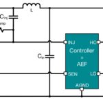
Another option is a damping network consisting of another capacitor and resistor.
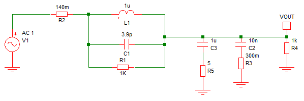
1uF has been added with 5 ohms of series resistance. The effect is shown below – green trace.
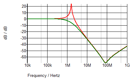
As you can see, the peaking has been removed and the high-frequency attenuation preserved. The resulting transient response is a well-damped transition, as would be expected from a clean looking AC response. The method you might use would depend on several factors:
- the frequencies you are trying to attenuate
- value of capacitance which are already present in your design
- the amount of voltage drop you can tolerate
- const constraints
The cost constraints can be important. If you have a large capacitance on the filter output anyway then the damping capacitor required will be even larger and so could start to get expensive and take up valuable space. A damping resistor will always be a cheaper option provided you can accept the lower high-frequency attenuation.
If you can tolerate a voltage drop then simply consider a small resistor instead of an inductor. I have found a resistor of 5 or 10Ωs can be quite effective at reducing noise in power supplies for analog circuits when you have large capacitance anyway and the cost is minimal and with none of the resonance drawbacks caused by inductors. You will only get a level of attenuation based on 5 or 10Ω compared to a ferrite bead or inductor where the impedance for attenuation purposes can be 1kΩ or more.

Leave a Reply
You must be logged in to post a comment.