Have you ever wondered which type of Printed Circuit Board (PCB) materials would be worth investing in to improve signal integrity? Would your high-frequency signaling work better with a tighter, more uniform weave in the core sheet of the PCB? What’s a high-frequency signal, anyway? When should you invest in a rigid, moisture-proof PCB?
Properties of PCB materials
The electrical properties of PCB material directly affect the overall performance and durability of circuitry. Some PCB material properties that may be of concern are the following:
- The dielectric constant (Dk) of PCB material affects impedance of the circuits. A PCB with a low and stable dielectric constant, even with changing frequencies and temperatures, is suitable for high-frequency [i] Otherwise, if a PCB is made of material with a poor Dk, transmission lines or traces on the PCB will change impedance in unpredictable ways.
- Electromagnetic waves are created from oscillating electric and magnetic fields. These waves can be absorbed in the dielectric layer of a PCB during signal transmissions, which leads to attenuation. (Attenuation is a measure of the loss of signal strength in a transmission).
- The measure of signal attenuation with respect to signal propagation is called Dissipation Factor (Df). A PCB material’s Df is a useful parameter to investigate when Signal Integrity (SI) is of concern. Preserving SI is a matter of combating causes of signal distortion, signal loss, crosstalk, ringing, and noise induced by a power supply. Signal strength is a major concern with respect to high-frequency signals and sensitive circuits. In many applications were the electromagnetic signals are feeble, the dissipation factor plays a vital role in preserving signal strength.[ii]
- The roughness of the copper surface on a PCB can also add resistance to a signal or add resistance in the circuit. Rough copper traces increase the resistance because the topography of the copper surface moves the signal up and down. Surface spikes can create an increase in capacitance, as well. Smooth copper can cost more but may be worth it to preserve signal integrity at RF frequencies.[iii]
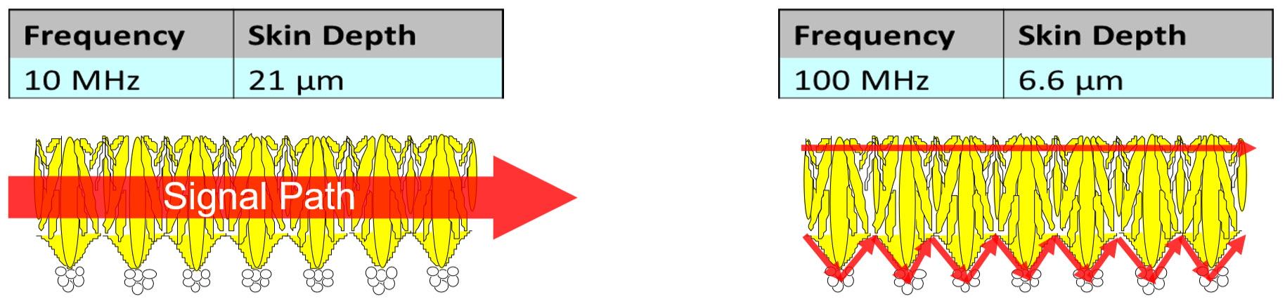
Figure 1: The current can tunnel below the surface profile and through the bulk of the conductor (image at left). The current is forced to follow every peak and trough of the surface profile increasing path length and resistance. (Image to the right). (Source: Webinar, isola-group.com)
- PCBs can have fiberglass sheet cores that are made up of strands of fiberglass yarn and epoxy resin. The dielectric constant differs across the sheet cores and is therefore inhomogeneous. For improved uniformity of dielectrics across materials, a densely woven fiberglass style can be used for the PCB core. The pre-impregnated material around the high-speed signal layers must be used for controlling impedance and signal issues. [iv]
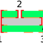
Isola is “a leading global material sciences company that designs, develops, manufactures and markets copper-clad laminates and dielectric prepregs used to fabricate advanced multilayer printed circuit boards (PCBs).”[v] Isola’s expertise includes knowledge on how to mitigate fiber weave effects of PCB sheet cores. Isola’s advice is to use more uniform glass (see Figure 2, below). The uniform glass weaves will have more uconsistent distributions of glass across the entire surface, which reduces variations in impedance for traces. You can use as wide a trace as possible in your layout, route the traces at an angle to the fiber warp and fill, route traces in a zig-zag fashion with respect to the fiber (see figure 2, below), and select materials that have resin and fiber dielectric constants that are as close as possible to each other. High frequency signals (>100MHz) are the most likely to be affected by non-uniform dielectric effects caused by the PCB weave. The fabric weave has a far lower impact as a non-uniform dielectric on a trace that’s carrying a signal at a lower frequency.
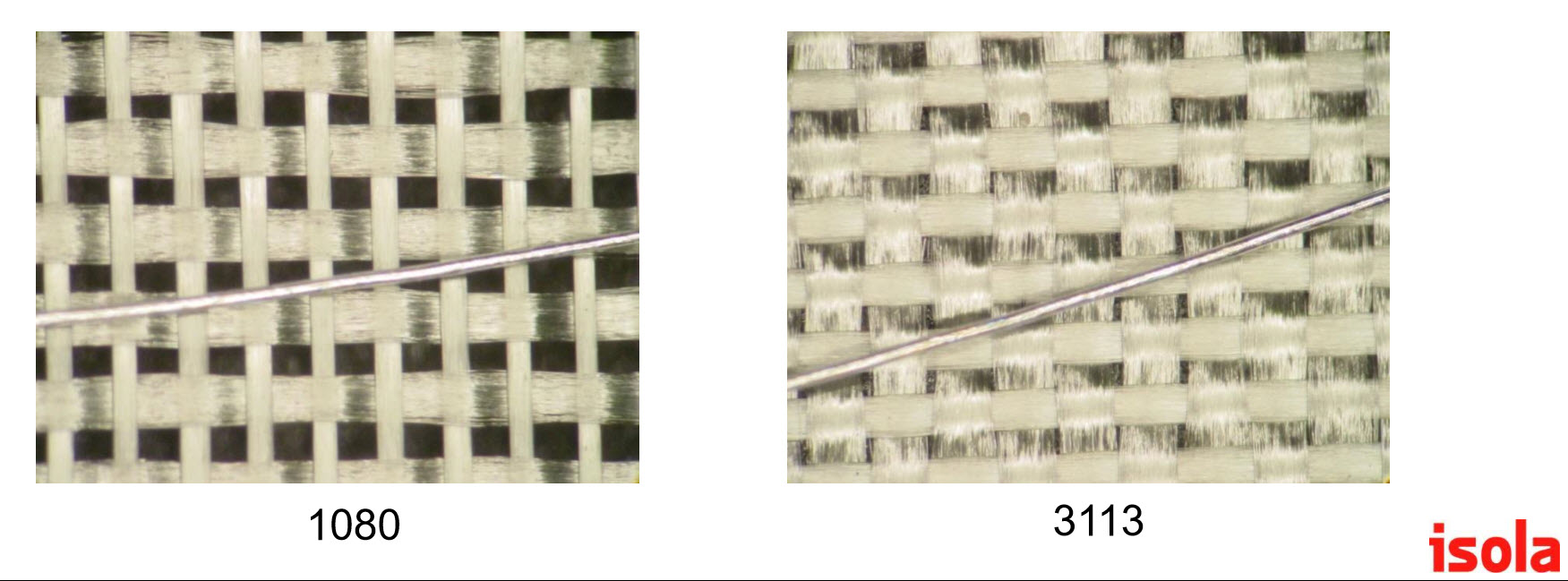
Figure 2: It’s possible to mitigate the dielectric effects that PCB fiber weave can produce. The weave on the left (1080) is not as uniform in construction as the weave on the right (3113). The wire shown on top of each weave is an example of how a trace should be imposed against weaves, which also improves the uniformity of the dielectric imposed by the fabric weave.
- Note that the dielectric of a PCB fabric weave can absorb moisture if it’s exposed to liquids or wicks moisture due to humidity. Moisture absorption affects the overall performance of a PCB. Generally, the moisture absorption value of a PCB dielectric is between 0.01 to 0.2 %. [vi]
- The ability of a PCB to bear stress is called “flexural strength.” A PCB bend test can be performed to determine a PCB’s ability to resist [vii]
This just scratches the surface of the available choices in PCBs beyond options in traces and the fabric weave that’s sandwiched (laminated) between PCB layers. However, if you are starting to hit a wall on improving a design’s signal integrity, especially with high-frequency signals (greater than 100 MHz or 10 Gbps), then you might want to begin investigating the options mentioned here. Not all PCB options are mentioned in Part I and II of this article, but it’s a start.
[i] https://www.microwavejournal.com/blogs/1-rog-blog/post/23743-selecting-pcb-materials-for-high-speed-digital-circuits
[ii]https://www.intel.com/content/www/us/en/programmable/documentation/nik1412632494319/nik1412632443320/nik1412632443951.html
[iii] https://www.microwavejournal.com/ext/resources/Webinars/2014/SLIDES_Isola_26feb14.pdf
[iv] https://www.intel.com/content/www/us/en/programmable/documentation/nik1412632494319/nik1412632443320/nik1412632443951.html
[v] https://www.isola-group.com/about-us/
[vi] https://www.mclpcb.com/pcb-material-selection-guide/
[vii] https://www.testresources.net/applications/electronic-printed-circuit-board-pcb-flexural-bend-test/

Leave a Reply
You must be logged in to post a comment.