In addition to the International Telecommunications Union (discussed in part 1 of this FAQ series), there are several organizations that define and regulate acceptable levels of conducted and radiated emissions from electronic devices. These various agencies have developed numerous standards generally based on the operational environment of the specific device. Effectively managing EMI is a complex task. This FAQ provides an overview of some considerations for managing conducted and coupled emissions.
The table below provides a summary of several areas covered by specific conducted emissions standards. In addition to these commercial, industrial, and consumer standards, there are a variety of military and aerospace standards for emissions. One of the most commonly-specified are the MIL-STD-461 test procedures that define the test levels and test limits of electronic equipment used by the US military. MIL-STD-461 covers a wide variety of conducted emissions and susceptibility tests as well as a number of radiated emissions and susceptibility tests.

Summary of main non-military standards for conducted emissions (Image: Texas Instruments)
Many systems, especially switch-mode power converters, employ filters to control conducted emissions. While effective, these filters add to system size and cost. They can be either internal to the design or added externally. Even if individual power converters or other sub-systems include internal EMI filters, the addition of an external filter may be needed in systems with multiple power converters or other EMI sources such as high-speed microprocessors. EMI is additive and the sum of the individual sources can easily sum to more than can be filtered by the already included filter(s). In other cases, a filter may need to be added to a system designed to meet less stringent EMI limits, but that is being used in a more noise-sensitive environment. Standard external filters can be single-stage or multi-stage and are offered in single-phase or three-phase designs.
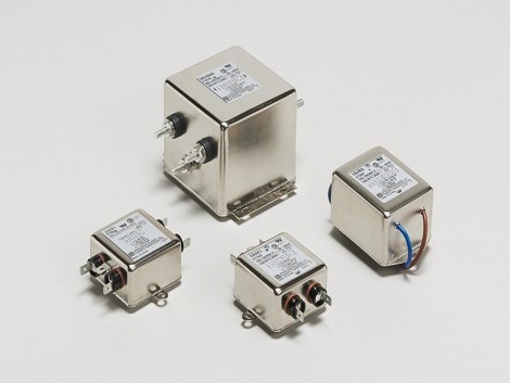
Examples of external EMI single-phase filters (Image: TE Connectivity)
Differential-mode and common-mode EMI
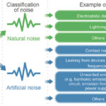
As illustrated below, conducted EMI can take the form of differential- or common-mode energy. Differential-mode noise can sometimes be referred to as “normal-mode” noise. Common-mode noise is created by leakage, usually through a stray impedance, such as capacitance or inductance, and is a form of coupled emissions.
Both differential- and common-mode noise can produce radiated EMI. In a typical design, common-mode noise produces much more radiated emissions than differential-mode noise. In fact, common-mode noise can produce as much as two orders of magnitude more radiated emissions than a similar level of differential-mode noise. That makes it particularly important to address common-mode noise to prevent excessive radiated emissions.
Differential- and common-mode noise characteristics (Image: ROHM)
As an example, common-mode noise can be suppressed using bypass capacitors connected between the power supply lines and ground. Bypass capacitors for the suppression of common-mode noise can be connected at both the input and/or the output. Common-mode noise can be further reduced by adding a pair of coupled-choke inductors in series with each power line. The coupled-choke inductors present a high-impedance path to the common-mode noise currents, forcing the currents to flow through the bypass capacitors and into ground.
Good EMC design is usually a two-way street. A design that emits unnecessarily large amounts of EMI (whether conducted to radiated) is also usually more susceptible to external EMI sources. So, reducing emissions also often results in lower electromagnetic susceptibility and improved system performance.
Testing for conducted EMI
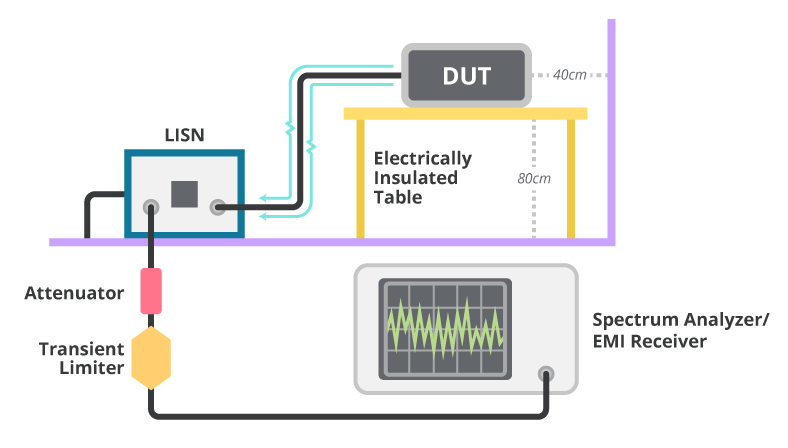 Basic conducted emissions testing setup (Image: CUI, Inc.)
While good design practices are required to control EMI, testing is also essential. Early testing can accelerate the certification process that is required before taking products to market. In-house testing does not generally replace certification by an independent testing laboratory. But in-house testing during product development can provide early identification of potential trouble areas and shorten time to market. Testing conducted emissions is relatively straight-forward. It requires a line impedance stabilization network (LISN), spectrum analyzer, and appropriately insulated/isolated testing set-up. Your spectrum analyzer supplier can usually provide specific instructions for implementing an effective conducted emissions test procedure.
References
An overview of conducted EMI specifications for power supplies, Texas Instruments
(Normal) Mode Noise and Common Mode Noise – Causes and Measures, ROHM
List of common EMC test standards, Wikipedia
The Importance of EMC Testing Early in Your Product’s Design, CUI, Inc.