A good designer anticipates that circuit performance and components will be imperfect or drift and employs various tactics to avoid the consequences.
When you spend a lot of time and energy designing, assessing, and debugging an analog signal chain from its sensor through front-end amplifiers and A/D converters, you have to face the reality that there’s an unavoidable gap between ideal principles and reality. This affects both the initial build as well as the many changes and drifts that will occur due to time, temperature, component aging, and other factors. A good designer takes these into account and accommodates them using an array of techniques and tricks.
It’s not just circuit designers who must address this situation, of course. Mechanical engineers must also allow for misalignments, thermal expansion, and more. Their solutions can range from using slots rather than round holes where possible in kit DIY furniture to providing adjustable leveling screws under appliances.
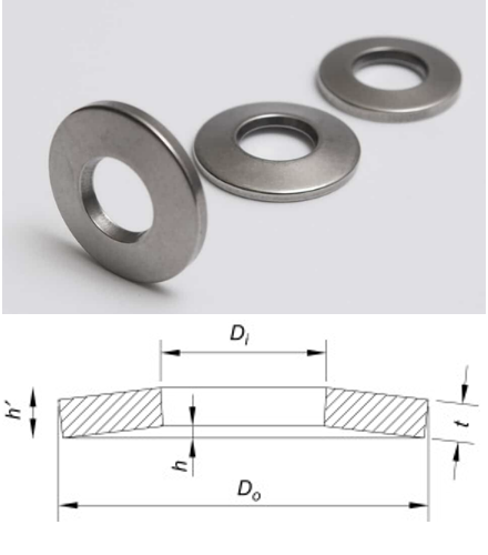
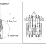
Critical mechanical bolted joints may even use Belleville washers (also called coned or spring washers), which have a domed shape to provide known amounts of compliance with shifts and dimensional changes in the bolted assembly, thus continuing to provide the full-surface contact needed (Figure 1).
This need for on-site adjustable assemblies extends especially to high-precision systems such as the James Webb Space Telescope (JWST) which has dynamic micro-adjusters for each of its mirror segments.
What are the options for circuit designers? There is, of course, no single best or right answer, as it depends on the size, cost, criticality, priorities, longevity, and other factors of the specific application. The three layers of tactics that are often used are 1) better components, 2) self-canceling topologies, and 3) adjustment and calibration.
1) For some situations, a good first-step tactic is to use better components, meaning those with tighter initial tolerance, with lower temperature coefficients, or that have been “aged” by the vendor or assembler to wring out initial drift; this is often done with voltage-reference ICs for precision applications.
2) A second design tactic is to use a circuit topology that inherently self-cancels some error sources. For this reason, “ratiometric” schemes are often chosen such as embedding a strain gage in a Wheatstone bridge with an identical dummy gauge in the bridge arm opposite the active gage (Figure 2). As a consequence, drifts due to time and temperature in the target gauge will be tracked and canceled by the pairing, as will variations in the power-supply rail. Rather than rely on absolute component values, this principle uses ratios of their values.
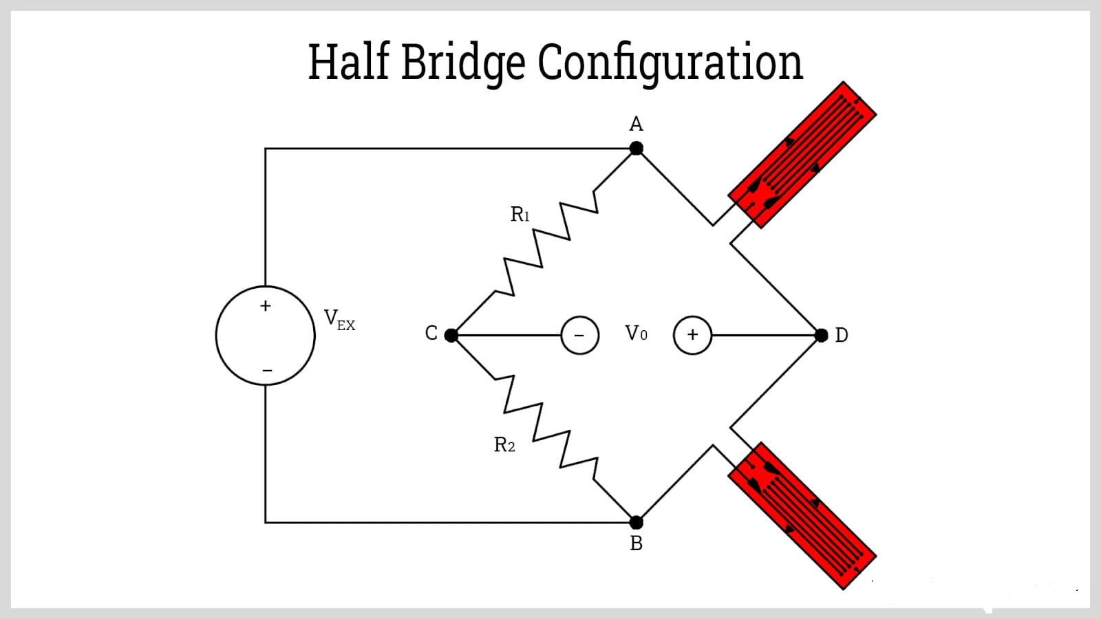
In other cases, a differential-circuit arrangement is used with two signal paths having identical characteristics, and only the difference between them is of interest. As these paths exhibit changes that track each other, it’s the difference between them which conveys the desired information.
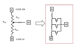
3) For situations where component selection and topology are insufficient, there’s the use of the trimming potentiometer (often called a trimmer or trimpot) or other calibration/adjustment arrangement. While the manually adjusted mechanical potentiometer is largely “yesterday’s component,” it has been supplanted in most (but not all) designs by an electronically adjustable version called a digipot, offering up to 128 or 256 distinct step values (Figure 3). Digipots allow adjustment of circuit factors such as offset, gain, and range directly via a processor or as directed by someone at a product’s screen.
While perfection and elegance in design is a worthy goal, sometimes the unavoidable realities of the components and physics of the situation work against that objective. An experienced designer accepts this scenario and plans for it using one or more tactics in the design implementation.
Related EE World content
Wheatstone bridge, Part 1: Principles and basic applications
Wheatstone bridge, Part 2: Additional considerations
Digipots as electronic potentiometers, Pt 1: Differences
Digipots as electronic potentiometers, Pt 2: Features
Digipots as electronic potentiometers, Pt 3: Enhancements
Stress & Strain, Part 1: Fundamental principles
Stress & Strain, Part 2: Implications for electronics


Leave a Reply
You must be logged in to post a comment.