Part 1 of this FAQ look at the operation of the CFB op amp and compared it to the VFB op amp. Part 2 continues the discussion of these two op amp topologies and their characteristics.
Q: How do you choose between VFB versus CFB?
A: Today’s CFB and VFB amplifiers have comparable performance, but there are certain unique advantages associated with each topology. The application advantages of current feedback and voltage feedback differ. In many applications, the differences between using CFB and VFB are not immediately obvious but are due to application-focused subtleties which their data sheets reveal.
A: Today’s CFB and VFB amplifiers have comparable performance, but there are certain unique advantages associated with each topology. The application advantages of current feedback and voltage feedback differ. In many applications, the differences between using CFB and VFB are not immediately obvious but are due to application-focused subtleties which their data sheets reveal.
Q: What is the primary operational difference between CFB and VFB op amps?
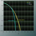
A: The primary difference between the CFB and VFB op amps is that the CFB amplifier does not have a constant gain-bandwidth product. This is in contrast to the VFB op amp, which does have this gain-bandwidth product characteristic (to a first-order approximation). While there is a small change in bandwidth with gain for the CFB device, it is much less than the 6 dB/octave roll-off of a VFB op amp, Figure 1. For a CFB op amp, the bandwidth is proportional to the feedback resistor. For every CFB op amp type, there is a recommended value of feedback resistor for maximum bandwidth, and increasing the size of the resistor beyond this value reduces the bandwidth.

Fig 1: The gain of a CFB op amp is relatively flat up to the point of roll-off, unlike a VFB device which has a fixed gain-bandwidth product; CFB bandwidth is set by a simple resistor.
Q: How does this affect the choice?
A: The application advantages of current feedback and voltage feedback differ and in many applications, these differences are not immediately obvious. Many of today’s CFB and VFB amplifiers have comparable performance, but there are certain unique advantages associated with each topology in a given application. For example, voltage feedback allows freedom of choice of the feedback resistor (or network) but this is at the expense of sacrificing bandwidth for gain. In contrast, current feedback maintains high bandwidth over a wide range of gains, but in doing so, it limits the choices in the feedback impedance.
Q: What are some of the other attributes and differences?
A: Another difference between the VFB and CFB amplifiers is that the inverting input impedance of the CFB amp is low (typically, just 50 Ω to 100 Ω), while the non-inverting input impedance is high (typically several hundred kΩ). Therefore, the inputs of the CFB amp are not balanced, as is the case with VFB amps, while balanced-impedance signal paths with differential amplifiers are a necessity in some signal-chains.
Q: Are there other issues?
A: Slew-rate performance is also improved with the CFB topology, since the available current which can charge and discharge the internal compensation capacitor is available on demand. It is not limited to a fixed value, as is generally the case in VFB topologies. This, with a step input, the current is increased (due to current-on-demand) until the feedback loop is stabilized. The basic current feedback amplifier has no fundamental slew-rate limit; instead, its limits are due to parasitic internal capacitances, and these have been greatly reduced with each successive generation of CFB devices. The combination of higher bandwidths and slew rate allows CFB devices to have good distortion performance while doing so at a lower power.
Q: This can be confusing; do you have a quick, high-level summary of the situation?
A: In general, VFB amplifiers offer lower noise, better dc performance, and greater freedom in selection of feedback. On the other hand, CFB amplifiers feature faster slew rates, lower distortion, but with feedback component restrictions.
Q: Any other points to consider?
A: There is a major caveat to the generalities presented above. Op amp processes are always evolving and improving, of course. Further, designers are always coming up with innovative design topology “twists” and “tricks” which partially or largely negate a given attribute, even if at the expense of some other characteristics. Therefore, it’s important to start with generalizations but also be open to the specifications of the many specialized, carefully tuned CFB and VFB op amps in vendor offerings, and be open-minded.
The References explore the use and design-in issues of CFB op amps, in addition to providing more details on their transfer function, models, and principles.
References
1. Analog Devices, MT-034 Tutorial, “Current Feedback (CFB) Op Amps”
2. Texas Instruments, Application Report SLOA066, “Current Feedback Op-Amp Circuit Collection”
3. Texas Instruments, Application Report SLVA051, “Voltage Feedback Vs Current Feedback Op Amps Application Report”
4. Linear Technology Corp., Design Note 46, “Current Feedback Amplifier ‘Do’s and Don’ts’”


Leave a Reply
You must be logged in to post a comment.