Digital potentiometers – digipots – are widely used, versatile, flexible, and feature-laden alternatives to classic mechanical potentiometers.
In addition to their “hands-off” controllability, digipots offer additional simplicity, design-in ease, and much lower cost than potentiometers. Among their other capabilities:
- Dual digipots are useful where two resistances must be adjusted independently but especially so when they must be at the same value. While two separate digipots ICs could be used, the dual device benefits from tracking resistance values despite tolerance and drift; quad devices are also available.
The devices are also designed to minimize crosstalk. A unit with two channels typically offers 0.5 dB channel-to-channel matching to minimize any volume difference; it also implements zero-crossing resistor switching to prevent audible clicks. (It also includes nonvolatile memory; the general utility of this feature is discussed below.)
- Linear versus logarithmic (log) settings: while trim and calibration applications usually need a linear relationship between the digital code and resultant resistance, many audio applications benefit from a logarithm relationship to better fit the “decibel” (dB) scaling of audio situations. Vendors offer digipots with a logarithmic transfer function versus the digital-code setting to meet this need.
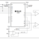
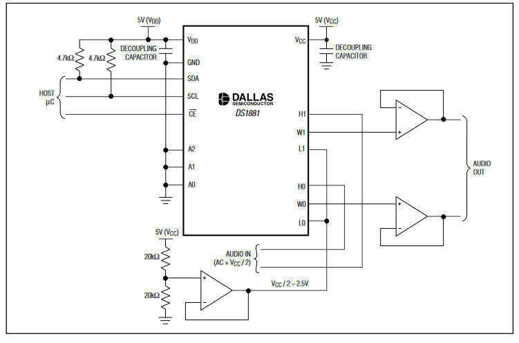
To meet this need, some vendors offer logarithmic digipots. The resistance value of each of the two channels in the Analog Devices/Maxim DS1881 can be set independently. A typical digipot configuration has 63 steps with 1-dB attenuation per step, ranging from 0 dB to -62 dB plus mute (Figure 1).
- The maximum voltage which the digipot can handle is also a consideration. Low-voltage digipots are available for operation with rails as low as +2.5 V (or ±2.5 V with a bipolar supply). In comparison, higher-voltage can work with rails up to +36 V (±18 V), useful in industrial and specialty applications.
Nonvolatile memory extends applicability
Basic digipots have many virtues but one inescapable weakness compared to potentiometers: they lose their setting after power is removed. At the same time, their power-on-reset (POR) position is determined by their design, usually to be at mid-range.
For many applications, however, that POR setting is unacceptable. Consider a calibration setting: once established, it should be retained until deliberately adjusted despite the removal of line power or battery replacement; further, in many applications, the “correct” setting was the one that was last used when power was removed.
Therefore, one of the remaining reasons for staying with potentiometers was that they do not lose their setting on power-up. To overcome this digipots shortcoming, it was common design practice to have the system processor read back the digipot setting during operation, then reload that setting on power-up. However, this created power-on glitches in their setting, even if only for a few hundred microseconds, and was often unacceptable for system integrity and performance.
To address this concern, vendors added nonvolatile memory (NVM) using EEPROM technology to digipots. With NVM, the digipots can retain their last programmed wiper position when the power supply is switched off, while one-time programming versions allow the designer to set the wiper’s power-on-reset position to a pre-defined value and even to re-program it if needed.
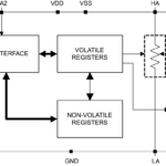
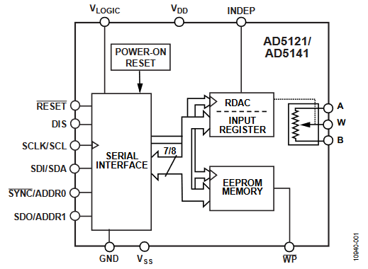
NVM enables other enhancements, as well. For example, users of the Analog Devices AD5141 (a single-channel, 128-/256-position nonvolatile digipot) can calculate the actual end-to-end resistance to an accuracy of 0.01% (one-hundred times better than the 1% accuracy of even higher-accuracy digipots) (Figure 2). They can then store associated calibration factors in the integral NVM to define the ratio of the “above wiper” and “below wiper” digipot segments for ratiometric accuracy, which is often the critical parameter in the circuit rather than absolute accuracy.
Digipot have other idiosyncrasies
While digipots are widely used to replace potentiometers where the traditional device is less desirable or impractical, they have some characteristics that require consideration. For extreme, the metal wiper of a potentiometer contacts the resistive element with near-zero contact resistance and usually negligible temperature coefficient. For the digipot, though, the wiper is a CMOS element with a modest but still meaningful resistance on the order of tens of ohms to 1 kΩ. If 1 mA of current goes through a 1-kΩ wiper, the resulting 1-V drop across the wiper may limit the dynamic range of the output signal.
Further, this wiper resistance is a function of both applied voltage and temperature, so it introduces a nonlinearity and thus distortion of AC signals in the signal path. The typical temperature coefficient of about 300 ppm/⁰C may be significant and so should be factored into the error budget for higher-precision designs; digipot models are also offered with much lower tempco specifications.
Conclusion
The digipot is a digitally set IC that replaces the classic rotary-knob electromechanical potentiometer in many system architectures and circuit designs. It reduces product size, but it also adds compatibly with processors and thus software, while offering greater accuracy and higher resolution (if needed) and other useful features. Digipots are available in a wide range of nominal resistance values, step sizes, and accuracies, while the addition of nonvolatile memory extends their capability and overcomes an important barrier to their use in many products.
Related EE World Content
What is a digital potentiometer?
What’s a logarithmic resistor ladder good for?
Advanced IC integrates instrumentation amp, auto-trimming, digital pots, analog switches
Single-turn potentiometers, encoders excel at rugged industrial apps
Micro-sized slide potentiometers for consumer, audio, medical, or industrial applications
References
VivaDifferences.com, “10 Differences Between Potentiometer And Rheostat (With Comparison Chart)”
Maxim Integrated Products, “Digipot Application Ideas”
Maxim Integrated Products, Application Note 1956, “Tips to Remember When Designing with Digital Potentiometers”
Maxim Integrated Products, Tutorial 1828, “Audio Gain Control Using Digital Potentiometers”
Maxim Integrated Products, Application Note 4051,” Using an Analog Voltage to Control a Digital Potentiometer”
Components101, “How does Digital Potentiometers work, why and where should you use them?”
Analog Devices, “Choosing the Correct digiPOT for Your Application”
Microchip Technology, AN691, “Optimizing Digital Potentiometer Circuits to Reduce Absolute and Temperature Variations”
Microchip Technology, AN1316, “Using Digital Potentiometers for Programmable Amplifier Gain”
Microchip Technology, AN1080, “Understanding Digital Potentiometers Resistor Variations”
Microchip Technology, “Digital Potentiometers Design Guide”