The electronic fuse is a powerful and versatile tool in the designer’s kit, but building one requires careful selection of the core amplifier; IC embodiments solve the problem.
Part 1 of this FAQ looked at the basic structure of the electronic fuse or e-fuse. This part looks at the requirements on the current sense amplifier (CSA) which is needed for the e-fuse, as well as e-fuses available as ICs.
Q: What are some considerations for the CSA?
A: The selection of the CSA used for sensing the voltage across the resistor is not trivial. While it is called a current-sense amplifier, that is somewhat of a misnomer: it actually senses a voltage which is proportional to the current. Still, many vendors classify these devices as CSAs since their characteristics are well suited to the e-fuse function.
Q: What is so special about the CSA, compared to a basic op amp used to sensing and amplify a voltage?
A: There are several points. First, the CSA is a differential amplifier (diff amp). This is because in most configurations, the resistor is not connected on the grounded side of the load (assuming the load even has a ground). Instead, is it connected on the high side and thus the CSA must measure the voltage without any ground connection.
Q: Is that all?
- Mo. The diff amp acting as CSA must be able to make its measurements despite high common-mode voltage (CMV). Consider the situation where the CSA measures the voltage across a restorer which is in-line with the high side of a motor operating at tens of volts (or higher), or at the top of a stack of series-connected batteries where the summed overall voltage is in a similar range.
The CSA must be able to sense that small voltage yet be unaffected or damaged by the presence of the high voltage which is common to both high and low sides of that sense resistor. For this reason, CSAs are uniquely designed to measure voltages on the order of 10-100 mV yet tolerate common-mode voltages 50-100 V (as well as negative CMVs) without degrading their accuracy or basic function (or even being damaged).
Q: What else is there?
A: A CSA must scale the voltage across the resistor with accuracy and stability. Although specifications vary, most resistors used for sensing are sized so that the voltage across them will be on the order of 10 and 100 mV maximum, so as to have minimal impact of the voltage delivered to the load along with minimum power dissipation.
However, this low voltage is not suitable for most analog circuitry, since it is easily affected by system noise, EMI/RFI, and other issues. So the CSA must scale it up to between 1 and 10 V in most designs. To do this, the diff amp configuration uses precise and matched scaling resistors to set the gain. These resistors must also track each other with identical temperature coefficients so that any temperature changes do not affect accuracy. Another important CSA requirement is ultra-low input offset voltage, so that the voltage across the sense resistor is much higher than the input offset voltage of the CSA.
Q: What else can an e-fuse do that a thermal fuse cannot do?
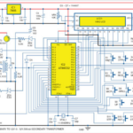
A: As with a conventional fuse, the e-fuse is connected between the power rail source and its load, Figure 1, and can do much more than a standard fuse. IC-based e-fuses such as the TPS25925x family of devices from Texas Instruments include additional functions and features including user-programmable undervoltage lockout, overvoltage clamp, auto retry, and start-up time which can be set by means of external components, Figure 2. That adjustable turn-on time is useful to keep in-rush current under control during startup and hot-swap operations, Figure 3. Despite its internal complexity, the e-fuse is fairly easy to use, and they are available from other vendors such as ST Microelectronics, Analog Devices, and ON Semiconductor, among others.
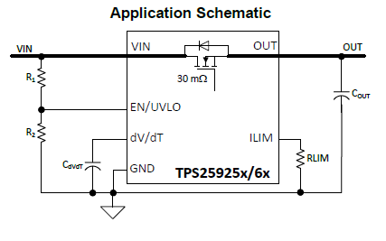
Fig 1: The e-fuse is easy to use, just like a standard fuse; it is inserted between the power source and its load. (Image source: Texas Instruments)
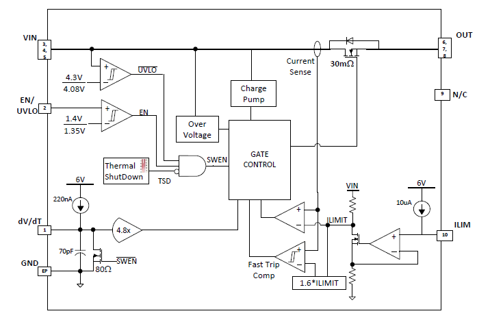
Fig 2: Within the e-fuse are may functional blocks and circuits which add features such as programmable threshold, delay, and turn-on rate, to cite a few; each enhances the versatility of this device and the role it plays in the system operation. (Image source: Texas Instruments)

Fig 3: Not only is the “trip” threshold of the e-fuse user programmable (left), but the e-fuse offers fast response to overcurrent conditions and restoration of current flow when fault condition is removed (right); top trace is input voltage, below that is output voltage, and lowest trace is output current: (Image source: Texas Instruments)
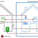
Q: Can an e-fuse be used along with a conventional thermal fuse?
A: Yes, and that is often done. The e-fuse acts as a first, fast, and flexible barrier or level of protection. The conventional fuse acts as a secondary backup and also allows the system to meet various regulatory standards which call for unequivocal action and complete open-circuit cut-off of the current flow, which an e-fuse cannot implement.
This FAQ has looked at the electronic fuse and what it takes to build one, or buy it complete in IC form. The e-fuse can be a stand-alone protection device or can be used in conjunction with the thermal fuse, depending on the application and regulatory mandates. Each has advantages and design-in considerations, and when used together they can provide a very rigorous protection mechanism.
References
- EEWorld Online, Fuses for power protection, Part 1
- EEWorld Online, Fuses for power protection, Part 2
- EEWorld Online, Options for current sensing, Part 1
- EEWorld Online, Load switches, Part 1: Basic role and principle
- EEWorld Online, Load switches, Part 2: IC implementations and benefits
- EEWorld Online, Programmable electronic fuse sustains 4 A over 8 to 48-V range
- EEWorld Online, Fuses that blow safely
- Analog Devices, LTC1153 Auto-Reset Electronic Circuit Breaker Data Sheet
- ST Microelectronics, STEF01 8 V to 48 V Universal Electronic Fuse Data Sheet
- Texas Instruments, PS25925x, TPS25926x Simple 5-V/12-V eFuse Protection Switches


Leave a Reply
You must be logged in to post a comment.