Unless you are an RF designer you probably haven’t thought much about intermodulation distortion. Harmonic distortion is more likely to have been of concern with low frequency circuits such as video and audio. Harmonic distortion, as the name suggests, creates unwanted components which are harmonically related to the signal. So, if you are amplifying 1kHz you will also end up with some 2kHz, 3kHz, 4kHz etc.
Depending on the circuit, you could find either the odd or even harmonics dominate the distortion. For example, crossover distortion tends to generate even harmonics and signal compression generates more odd harmonics. There is a distortion analysis in SPICE using .DISTO but it is of limited use. A more flexible method for SPICE simulation is to make an FFT plot of the output signal. As an example, with a simple bipolar transistor amplifier driven at a fairly high level, this is the output FFT from a 1kHz signal.
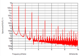
The fundamental measures 500mV with the second harmonic at 2kHz being 40mV. The third harmonic at 2mV. The higher order harmonics are progressively smaller. Adding 60Hz to the same signal and plotting the FFT, you get not only 60Hz and 1kHz but many other frequencies. In this case the 60Hz signal is the same amplitude as the 1kHz signal and that is shown in the FFT as 500mV.
You have harmonic components from the 60Hz e.g. 120Hz, 180Hz but you also have some 940Hz and 1060Hz, 880Hz and 1120Hz as well as components 60Hz and 120Hz away from 2kHz, 3kHz etc. The these are the intermodulation products. The non-linearities in the amplifier are acting like a multiplier or mixer and so creating components which are the sum and difference of the two frequencies. In this case the 940Hz signal is twice the size of the second harmonic at 80mV so this intermodulation product is only 16dB below the actual signal.
If you remember your math, sin(x).sin(y) = Ω[cos(x-y)- cos(x+y)]. In our case, x=wt where w = 2pf where f=1kHz for x and f=60Hz for y. So, you can see where the additional components come from. But does it really matter?
One reason I was revisiting intermodulation distortion recently was to determine if it could be detrimental to the noise of a system. The system in question has very low signal levels and 50/60Hz power line interference which has a notch filter part way through the amplification chain. It occurred to me that intermodulation distortion will reduce the effectiveness of that approach. If you add a 60Hz filter to the example shown above, you will remove the 60Hz but none of the harmonics or components centered around 1kHz, 2kHz etc. While the system in question has 180Hz filters as well, they still can do nothing for the higher frequency components, nor for the 120Hz in this example. While the simulations have been made extreme to help illustrate what intermodulation distortion is and a bipolar amplifier was used which will be a lot worse than a feedback amplifier, the principle is still valid and the system in question actually has a common source JFET amplifier which could be a significant source of harmonic/intermodulation distortion particularly with high levels of 60Hz.
With an opamp the results are a lot better, as would be expected from a feedback amplifier. With the LM324 the 940Hz signal is 103dB below the 1kHz signal with equal amplitude 60Hz/1kHz input signals. In general. intermodulation distortion is a lot less of a problem with feedback amplifiers compared to discrete, non-feedback amplifiers but it is always worth remembering to check if you are working on circuits with very small signals with unwanted signals you expect to filter out later.
While there are other design tools for simulating the performance of non-linear systems for RF design such as Harmonic Balance Analysis, an analog designer working at low frequencies is unlikely to have access to those tools. With SPICE the AC analysis only looks at the response to a single input frequency and with a very small signal. It doesn’t look at response of multiple input signals with large signal levels. It is for that reason that you need to resort to a transient analysis where you can choose the number of signals and their amplitude and rely on FFT for analyzing the results.


I don’t know where the author’s experience of crossover distortion was gained, In my experience, crossover notches occur on both positive and negative going slopes, which indicates a symmetrical non-linearity (it’s not hard to imagine why) and therefore it generates predominantly odd order harmonics that usually extend right through the frequency range and beyond the audible limit, which is why it is particularly unpleasant.
By contrast, “compression” might generate odd only or all harmonics, depending of whether the stage compressing is of symmetrical or asymmetrical topology. Except for low level FET amplifiers and specially contrived circuits, you will rarely encounter a circuit that gives rise to only even harmonics, and we haven’t yet even considered the effects of feedback!
The same general trends will be noted with regard to intermodulation, and the author has missed a trick in not exploring this in more detail. All in all, the article delivered a lot less than it promised.
You are correct in that the second harmonics are not from crossover distortion. I was thinking of opamps such as the LM358 which can have higher second harmonic than third depending on the configuration but that is most likely due to other effects and I incorrectly related the two. It is not improved by loading the output – the recommended solution for the crossover distortion problem on that opamp. Second harmonic distortion is something I have seem with opamp configurations with an asymmetric output stage where source and sink performance are unequal. Even newer opamps such as the OPA690 have more second harmonic distortion than third harmonic although it is dependent on exact configuration and circumstances (drive level, gain, inverting or non-inverting etc). The OPA690 gives quite a few second and third harmonic graphs. This brief article was really about the effects of intermodulation distortion rather than harmonic distortion, even if the causes are linked.
A short article can only scratch the surface of a complex topic. I aim to give food for thought and further reading.
Yes – I’m not going to say much other than it was very generalized and I’ve read it all before. Also I don’t think much of spice as a circuit analysis tool.
I would be interested to learn what tool you do recommend for circuit analysis if not SPICE. I doubt there are any analogue ICs designed in the last 30 years, in which the designer has not used SPICE as their main circuit tool; indeed the most design flows almost preclude any other approach.
My experience is that when someone says they don’t rate SPICE as a tool, it’s because they have never bothered to learn how to use it properly. We can probably exclude Bob Pease from that generalisation, but that’s because he was wary of people using SPICE in the absence of an intuitive understanding of how basic stuff worked, which is fair enough. I reckon human error and bad models probably account for 98% of occasions when SPICE analysis doesn’t produce a pretty good prediction of real world behaviour. Part of the skill in using a tool like SPICE is to recognise when garbage out is simply due to garbage in.