Many devices have been built for measuring electric charge. One of the first was the gold-leaf electroscope. When a charged object touches the metal knob at the
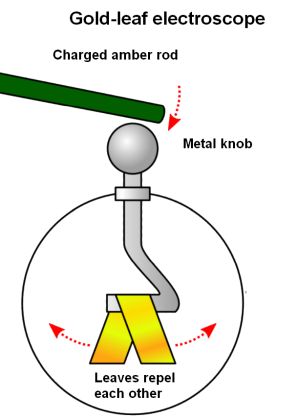
outer end of the rod, the charge flows down to the leaves. The leaves diverge due to the repulsion of like charges they have received. The degree of divergence of leaves gives the measure of amount of charges. This early instrument was simple to construct and highly sensitive.
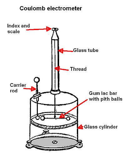
The Coulomb electrometer operates by means of twisting thread holding a bar and is more sensitive than the gold-leaf apparatus. It contains a glass cylinder with a glass tube on top. Hanging down through the glass rod is a gold thread, at the loose end of which is a moving bar (Originally of gum lac, a resin-like substance secreted by certain insects and used in varnishes and sealing wax. Later on, a needle was used.). A gilt pith ball (Pith is the spongy material found inside most vascular plants, and a pith ball has a surface coated with conductive material.) sat at each end of the bar and served as a conductor. Then a second bar with charged pith ball conductors would be introduced into the glass cylinder through an aperture (i.e. a hole in the side). This would repel one of the movable balls. An index and scale is attached to the glass rod, and the amount of thread rotation required to bring the balls together relates precisely to the amount of charge on the introduced rod, called a carrier rod.
 Another design called the Peltier electrometer measures deflection by balancing the electrostatic force with a magnetic needle. The Bohnenberger electrometer consists of a gold leaf suspended vertically between the anode and cathode of a dry pile (basically a series of paper discs, coated on one side with silver leaf arid and on the other with thin leaves of zinc, all piled up in a glass tube). Any charge applied to the gold leaf causes it to move to one of the poles, which indicates the sign and magnitude of the charge.
Then there are attraction electrometers where a plane conducting plate forms one pan of a balance which was suspended over another insulated plate which could be electrified. The attraction between the two plates was balanced by a weight put in the opposite pan. The quadrant electrometer by Lord Kelvin is considered to be the most sensitive form of electrometer yet devised. Here a flat paddle-shaped needle of aluminum foil is supported by a bifilar suspension consisting of two cocoon fibers. This needle is suspended in the interior of a glass vessel partly coated with tin-foil on the outside and inside, forming a Leyden jar. In the bottom of the vessel sits sulfuric acid. A a platinum wire attached to the suspended needle dips into this acid. Charging up the Leyden jar keeps the needle at a certain constant high potential. The needle is enclosed by a sort of flat box divided into four insulated quadrants. The opposite quadrants are connected together by thin platinum wires. These quadrants are insulated from the needle and from the case, and the two pairs are connected to two electrodes.
The instrument can be used to determine the potential difference between two conductors by connecting the two conductors to the two opposite pairs of quadrants. The needle in its normal position is symmetrically placed with regard to the quadrants and carries a mirror that reflects a light to note the displacement. If the two quadrants are at different potentials, the needle moves from one quadrant towards the other, displacing the image of a spot of light on the scale.
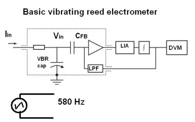
Modern electronic instruments for measuring electric charge find application in areas such as studying the ionizing effects of cosmic rays, determining absorption spectra in chemical analysis, and counting ions in gas chromatography. Among these devices is the vibrating reed electrometer which uses a capacitor that has a vibrating reed as one of its plates. Here a dc input current generates a dc voltage in a vacuum gap capacitor which is driven by a signal source via an electromagnet such that it oscillates at 580 Hz. This vibration induces an ac current that is amplified and subsequently rectified by a lock-in amplifier. The output of the LIA is integrated to get a rising output voltage that is fed back via a simple first-order RC low pass filter to a feedback capacitor (also a vacuum gap cap). The feedback loop minimizes the ac signal measured by the LIA and thus ensures the input voltage stays at 0 V, i.e., nulling the charge on the primary capacitor. In this way, a constant dc current causes a linear ramp of the feedback voltage. A high-accuracy digital voltmeter triggered by an accurate time base
determines the unknown current.
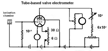 Valve electrometers employ high-gain vacuum tubes to accurately measure currents as small as 1014 A. The current between the vacuum tube filament and anode varies with changes in potential of a third electrode, the grid. It is different from the ordinary triode tube in that it is constructed to have a resistance as high as 1016 Ω between the control element and the other electrodes under normal operating conditions. The vacuum tube electrometer determines the rate at which charge builds up on the grid; there is a direct relation between the change in the current between the filament and the anode and the charge built up on the gird.
Solid-state electrometers generally replace the vacuum tube with one or more FETs and include display and data-logging capability. Today’s electrometers measure charges with 10 fC resolution, currents with 100 aA resolution, and resistances up to 200 TΩ. Closely related to the electrometer is the picoammeter, designed for measuring currents of less than 100 nA. Picoammeters are characterized by a low voltage burden that lets them function much more like an ideal ammeter than a DMM.
Typical tasks for modern electrometers include measuring resistances in the gigaohm and higher ranges for characterizing high megaohm and gigaohm resistors, determining the resistivity of insulators, and measuring the insulation resistance of printed circuit boards. Electrometers are also used for volume resistivity measurements, the electrical resistance through a one-centimeter cube of insulating material, expressed in ohm-centimeters; and for surface resistivity measurements, the electrical resistance between two electrodes on the surface of an insulating material, usually stated as ohms per square. Capacitor leakage, for example, is measured by applying a fixed voltage to the capacitor and measuring the resulting current. The leakage current will decay exponentially with time, so it’s customary to apply the voltage for a lengthy soak time before measuring the current.