The electronically controlled, cam-free internal combustion engine seemed like a good idea, but technical and market realities stifled its acceptance.
The previous parts of this article discussed the operation of the standard, cam-driven internal combustion engine with a mechanically driven intake and exhaust valve pair for each cylinder. This section looks at the alternative of an electronically controlled camless system.
For many years, automotive engineers have known that if they could implement more control and adjustability over valve timing, they could boost engine output power and reduce pollutants in the engine exhaust. This approach begins with a smart timing system, which involves an engine-crankshaft angle sensor to provide an input signal and a processor for executing algorithms and then drives electronically controlled valves. This combination would be a natural fit for engineers to design in as part of engine control as implemented in the engine control unit (ECU).
Three critical elements are needed to make this happen, in adding to the crankshaft angle sensor (which is now standard in nearly all vehicles: enhancements to the ECU algorithms, power-management ICs to drive the electronic valves, and the electronic valve actuators themselves. The goal is a flexible valve-control system that improves performance while reducing emissions. Sometimes called a “camless” system, this control allows engine control subsystems to vary valve timing, valve lift, and compression ratio in response to engine load, temperature, fuel/air mix, and other factors. The timing could be continuously adjusted to dynamically balance engine performance with respect to parameters such as power, emissions, and fuel efficiency, depending on the immediate priority.
Further, with electronically controlled camless valves, the timing and operation of each valve is independent of the others, which offers significant operational flexibility. For example, if the engine’s load is light, it even allows the control module to deactivate cylinders to save fuel. Such a system could even compensate for component wear over time and engine life.
Not easy to implement
Conceptually, it is architecturally uncomplicated to replace a mechanical valve train with a processor-based one. In practice, though, major obstacles hinder successful implementation, in addition to the long and established track record of (and comfort with) the existing approach. It’s easy to think, “What’s the big deal naively? Just use the digital output of a processor to drive an actuator which controls its respective valve,” but there are major limitations, standards, and long-term issues that automotive engineers face.
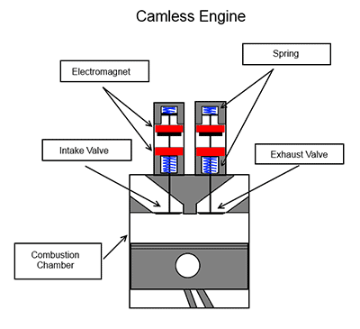
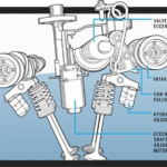
There are two approaches available to actuate a valve electronically. The first uses a solenoid, a reliable and well-understood transducer for converting an applied current into linear motion and static force. However, challenges exist if you use a solenoid as an actuator under the hood (Figure 1).
First, the current pulse needed to activate the solenoid with the force and speed required in this application is large and difficult to get from the 12 V supply of the vehicle without heavy supply cables. For this reason, the solenoid approach must wait until vehicles switch from 12 V supplies to the more-efficient 42 V standard that automakers are already phasing in over the next few years.
A hefty MOSFET or similar electronic switch is also needed to handle the current for each solenoid, with an intervening driver to interface between the relatively modest digital output drive of the valve-timing processor to the MOSFET, which drives the solenoid as actuator. Although this solenoid operates at a moderate duty cycle, its overall rate of operation is high enough that there are self-heating problems. Further, the heat under the hood, especially high near the engine, aggravates these problems. The number of lifetime solenoid cycles is in the millions, and the combination of heat and operating cycles brings major reliability concerns.
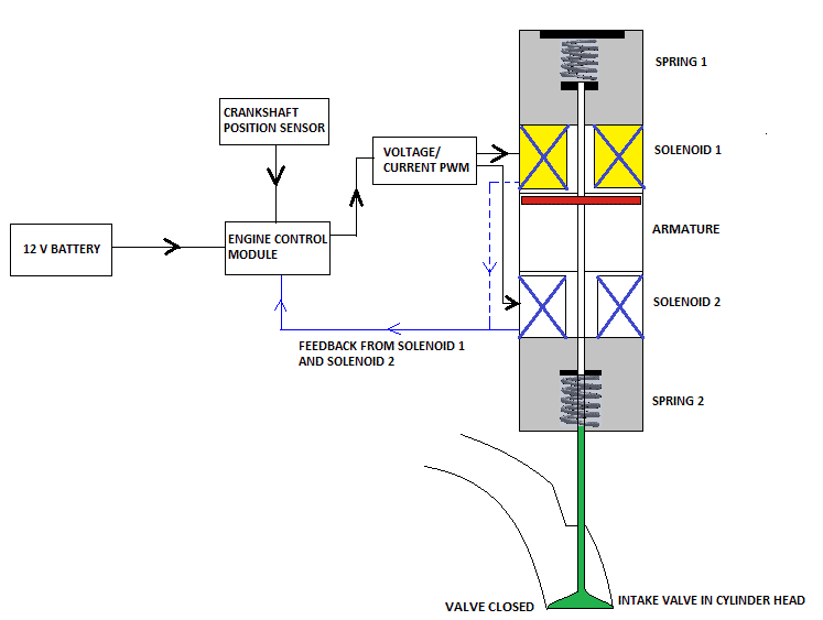
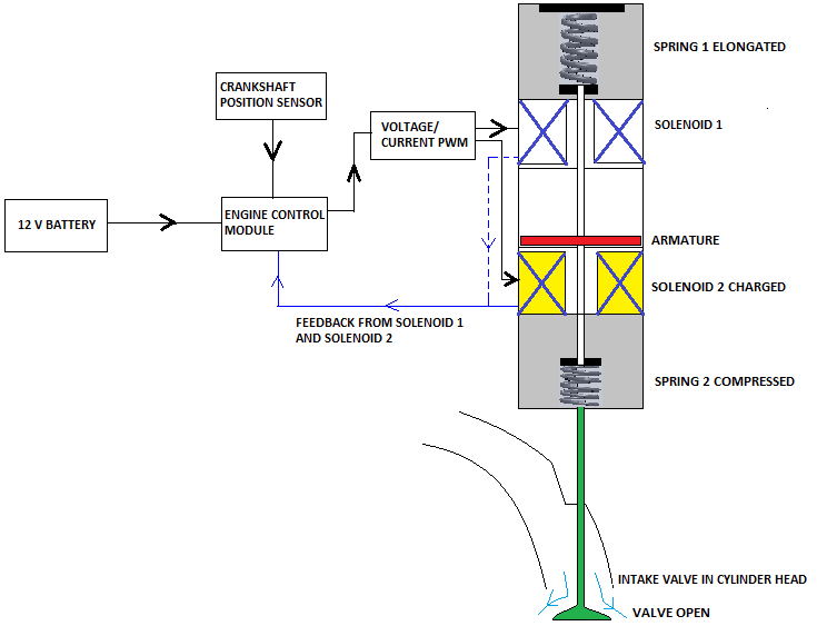
Solenoids alone can actuate in either direction when the power supply to them is reversed. But this is complicated to do in a single-supply, grounded environment, such as a car or truck. It is more practical to use a spring to develop the return force. The solenoid then has to open the normally closed valve by overcoming the spring’s force. A solenoid can be designed with a pair of springs in which the applied force overcomes the return spring force while a helper spring pushes the solenoid in the actuate direction and reduces the needed holding current. Other approaches use a pair of solenoids in a push-pull arrangement, with one to close and the other to open the valve (Figure 2 and Figure 3). However, all of these factors add complexity and cost to the design.
Also, solenoids are on/off actuators with relatively fixed force-versus-distance characteristics. Without springs or other external forces, the solenoid’s force is initially lowest as the magnetic field pulls the core slug toward its center; the force is greatest at the center at the final resting point of the actuator travel.
Consequently, a solenoid slams the valve closed fairly hard, which aggravates wear on the valve seals unless a damping mechanism is added, such as springs or other components. (Recall that the mechanical cam-based valve train solves this distance/force problem by carefully shaping the profile of the cam lobes.) One approach is to build a closed-loop solenoid with a sensor that monitors the core’s position and use this information to modulate the drive current. But this approach also adds complexity and cost to the design.
An alternative to the solenoid is the hydraulically actuated valve mechanism. In this design, pioneered by Sturman Industries (Colorado), now owned by Virtual Energy, a small and fast-acting electrohydraulic actuator provides the “muscle” for valve motion under the control of an electronically controlled digital valve (Figure 4).
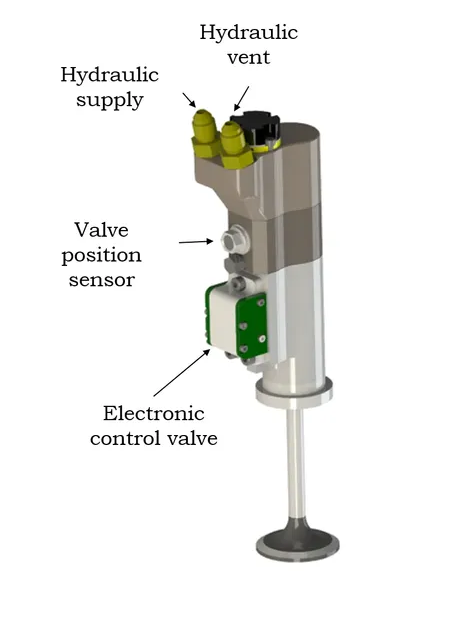
The fluid power travels via the fuel-injection system and pump. This digital valve uses residual magnetism (the magnetic field that remains after you magnetize an object) to hold the valve open without any applied current after the current pulse moves the valve. (In addition to Sturman, there are efforts underway by UK-based Camcon Automotive Ltd and Sweden-based FreeValve, a subsidiary of Koenigsegg Automotive.)
Engineers developed this type of valve during the Apollo space program, and Sturman modified it for engine control. According to Sturman, the valve offers much more pressure combined with precise position control because the hydraulic valve is a linear transducer. The current flows through two small coils on either side of a small spool that controls fluid flow rather than through a large solenoid; as a result, the system-response time is about five times faster with the coil-based design than with the solenoid-based configuration. The processor can modulate the spool motion – and thus fluid flow and power-to yield the desired force and distance profile.
The final section of this article looks at the status and acceptance outlook for electronically controlled, camless engine valves.
Related EE World Content
Understanding stop/start automobile-engine design, Part 6: Responses and workarounds (has links to previous Parts 1 through 5)
Digital Valves Open Up New Possibilities For Engines
Single element, tooth-detecting speed sensor IC
References
- Car and Driver, “Variable Valve Timing Explained: An Appreciation of How Quickly Engines Operate”
- New Atlas, “World’s first fully digital valves open up engine possibilities”
- Motor Authority, “Fully digital valves could change the future of the combustion engine”
- Motor Authority, “ ‘Engineering Explained’ tackles Koenigseggs camless engine”
- Clemson University, “Electronic Valve Timing Control”
- Clemson University, “Camless Engines”
- Motor1, “Fully Digital Valves Could Massively Improve The ICE”
- Wikipedia, “Camless Piston Engine”
- Top Gear, “Here’s how the Koenigsegg Gemera’s 600bhp camless engine works”
- Hackaday, “Where Are All The Camless Engines?”
- The Wall Street Journal, “Gas Engines, and the People Behind Them, Are Cast Aside for Electric Vehicles”
- Wikipedia, “Desmodromic valve”
- Virtual Energy, “Camless Hydraulic Valve Actuation (HVA)”
- Machine Design, “Improving Car Engines with Advanced Variable Hydraulic Valves”
- Skill-Lync, “Design and MBD Simulation of IC Engine Valve Train and FEA Analysis of Rocker Arm”
- University of Waterloo, “New Fully Flexible Variable Valve Actuation System”
- University of Waterloo, “New Fully Flexible Variable Valve Actuation System”
- University of Waterloo, “Hydraulic Variable Valve Actuation System: Development & Validation”


Leave a Reply
You must be logged in to post a comment.