RF power amplifiers consume lots of energy, which is a concern associated with 5G. Envelope tracking helps reduce power consumption but has tradeoffs.
In How to calculate RF power amplifier efficiency, we covered the basic concepts of power efficiency (PE) and Peak-to-Average Power Radio (PAPR) for amplifiers. We also explained how high Peak-to-Average Power Ratio (PAPR) in a wireless signal is a barrier to achieving the best power efficiency. Because of the high PAPR in wireless modulation, new approaches are being used for power amplifier (PA) design. One of these design approaches is known as envelope tracking, because the PA supply voltage tracks the envelope of the RF signal.
Envelope tracking is not really a new idea. Loy Barton is often credited for originating the technique in the early 1930s. Barton was working on ways to improve power amplifier efficiency, including inventing the Class B amplifier. This was during the era of AM broadcasting and vacuum tube power amplifiers. Power amplifier efficiency was a big issue back then as broadcast stations strived to put out the biggest signal possible. More recently, envelope tracking has been applied to semiconductor-based amplifiers for wireless base stations and mobile devices.
Fixed Power Supply
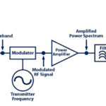
Figure 1 shows a conventional PA setup. Wireless transmitters usually have a digital baseband section that operates using inphase and quadrature (I/Q) values for the digital modulation. (See Digital modulation basics, part 1 for more on I/Q.) An upconverter translates the baseband signal up to the frequency band of interest, which is then amplified by the PA. With a conventional PA, the power supply (VS) provides a constant, reliable voltage that sources sufficient current to keep the PA operating correctly. The PA must have a supply voltage that is large enough to handle the peak power and this is where the PA is most efficient. Most of the time though, the PA is operating at lower output power and lower efficiency.
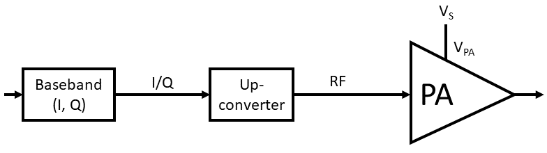
Figure 1. A conventional power amplifier uses a fixed supply voltage.
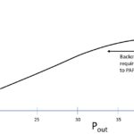
Typically, PAPR ranges from 5 dB to 13 dB, depending on the particular modulation format. As an example, at 10 dB PAPR, the peak power is 10 times the average power. A PA capable of producing 10 W of output power will, on average, be coasting along at just 1 W of output power.
Figure 2 illustrates this phenomenon graphically, showing the wasted power that occurs when there is a significant difference between the supply voltage and the signal voltage. When the signal is near the peak, the PA operates very efficiently but when the signal level drops off, a lot of power is wasted.
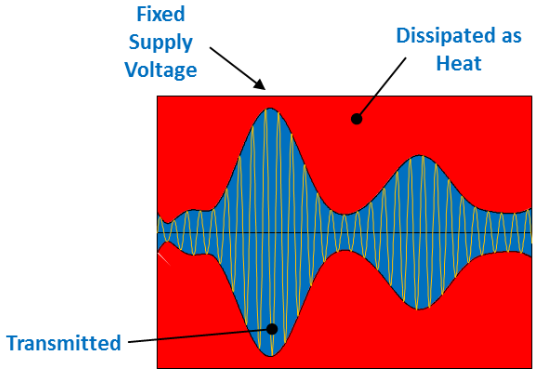
Figure 2. A conventional power amplifier uses a fixed supply voltage, often wasting power when the signal level is low. Image: Qualcomm
Variable Power Supply
The key idea of envelope tracking is to vary the supply voltage in real time to meet the PA supply voltage needs. When the signal peaks, the supply voltage is driven higher but when the signal level drops, the supply voltage drops along with it. As shown in Figure 3, this technique can dramatically decrease the amount of power wasted in the circuit.
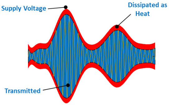
Figure 3. An envelope tracking power amplifier system varies the supply voltage, tracking the required signal level. Image: Qualcomm
Figure 4 shows a PA system employing envelope tracking. The envelope detector monitors the magnitude of the baseband signal. This could be an analog circuit but most of today’s baseband systems are digital so the envelope detector is also digital. The envelope detector uses the I/Q baseband data to calculate the magnitude of the signal in real time.
![]()
Figure 4. An envelope tracking power amplifier tracks the signal level and adjusts the supply voltage for maximum efficiency.
The envelope shaping block translates the envelope level to the desired supply voltage. This could be a straight-line function but more likely the system design will include some nonlinear shaping that optimizes the PA’s overall performance. Designers usually impose a lower limit on the PA supply voltage so that the circuit remains biased even if the signal goes away.
The Envelope Tracking Power Supply (ETPS) uses the envelope shaping output to produce the variable supply voltage (VPA) that goes to the PA. The ETPS is shown as an amplifier symbol to emphasize that this block must have dynamic performance normally associated with an amplifier: bandwidth, noise, gain, and accuracy. This is not a simple DC voltage regulator. The ETPS must have sufficient bandwidth to keep up with the modulation rate, which means having a bandwidth roughly two to three times the modulation bandwidth. LTE has channel bandwidths up to 20 MHz, requiring ~50 MHz in ETPS bandwidth. With higher throughput, 5G channels require even higher bandwidth. To maintain overall power efficiency in the system, the ETPS must itself be power efficient.
The two main paths in the envelope tracking system, the signal path through the PA and the envelope tracking path, must be time synchronized. The PA supply voltage must respond to changes in the signal envelope at just the right time — not too early and not too late. Mismatches between the paths can reduce the power efficiency and introduce distortion into the transmitted signal. A delay-matching block may be added to the system diagram, which facilitates this delay matching requirement.
System Design
The basic concept of envelope tracking is relatively easy to understand. The implementation of this design approach is, however, much more complex than using a fixed-voltage power supply. The ETPS is a high-bandwidth amplifier able to supply enough power for the PA to function properly. The PA is often the most power-hungry device in the system, requiring high current from the ETPS. The ETPS must also have low output noise to avoid degradation of the RF signal.
Sometimes the PA gain may change with supply voltage, which can introduce amplitude modulation onto the RF signal. This may limit how much voltage change can be tolerated on the PA supply. It is important to understand the characteristics of the PA and use the envelope shaping to optimize the overall performance of the system.
Envelope tracking is one design method that can improve PA efficiency. In the next article, we’ll look at another approach: the Doherty Amplifier.
References
- “Introduction to Envelope Tracking,” G. J. Wimpenny, Qualcomm, https://www.cambridgewireless.co.uk/media/uploads/files/Radio_SIG_Event_22.5.18_Introduction_to_Envelope_Tracking_-_Gerard_Wimpenny.pdf.
- “Envelope Tracking and Digital Pre-Distortion Test Solution for RF Amplifiers,” Application Note, Rhode and Schwarz, September 2017. https://www.rohde-schwarz.com/us/applications/envelope-tracking-and-digital-pre-distortion-test-solution-for-rf-amplifiers-application-note_56280-54791.html.
- “Loy Barton, a Forgotten Radio Pioneer,” James E. O’Neal, Radio World, July 2017, https://www.radioworld.com/columns-and-views/loy-barton-a-forgotten-radio-pioneer.
- “How to Use Envelope Tracking to Improve Power Amplifier Efficiency,” Andy Howard, Keysight Technologies, February 2015. YouTube video, https://youtu.be/Y72sl7Xo8rA.
Related articles:
- What are amplifier classes and their power efficiencies?
- RF power measurement, Part 1: Why and where
- RF power measurement, Part 2: What and how
- Analog and digital modulation and modulation measurements
- How to calculate RF power amplifier efficiency
- Digital modulation basics, part 1