There are currently a large number of serial protocols in use. Many oscilloscopes include the capability to decode and display data sent over widely used serial buses. Recently, a blog on the Tektronix website detailed which serial decode packages engineers most commonly configure on the Tektronix scopes they order. The buses that turn out to be most widely used are those in inter-chip, peripheral, or network interfaces across many industries. Specifically, in descending order, the serial buses most likely to be examined via scopes are I2C, SPI, RS-232, CAN, USB, and Ethernet.
It may be useful to review some of the basic serial protocol terminology in sorting out these protocols. Serial protocols fall into two categories, synchronous and asynchronous. In a synchronous serial interface, the lines carry and are governed by an external clock. All devices share the same clock. Often, the serial interface is simpler to implement and faster, but at least one extra wire is required to connect all devices. SPI and I2C are synchronous interfaces.
Asynchronous communication is not timed by an external clock. This minimizes wires and pins, but additional efforts are needed to transfer data. The transfer process involves data bits, synchronization bits, parity bits and baud rate. In all of this, there is considerable flexibility, and that’s where different protocols enter the picture. In all cases, identical protocols are to be configured for all devices.
The baud rate is a measure of how fast data transfers over a serial link. It is expressed in bits per second (bps). The value is important because it determines how long the transmitter holds the serial line high and low and how long the receiver samples that line. The most common baud rate is 9,600 bps.
Blocks of data are sent in packets or frames. They are created by combining synchronization and parity bits and applying them to the data. The standard number of data bits in each packet is eight, but this can vary from five to nine bits. Both devices have to agree on the order of the bits. It can be most significant bit (msb) first but more often it is lsb first.
The start bit and one or two stop bits comprise the synchronization bits, and they are appended to the outside of the packet. The start bit is indicated by one of the idle lines going from logic 1 to logic 0. The stop bit initiates the idle state by remaining at logic 1.
In addition, there are parity bits, the purpose of which is to detect errors. Parity may be even or odd. The parity bit is produced by adding all bits in the data byte. Parity is not widely used, but it is helpful in a noisy environment. The downside is that it slows data transfer.
At the physical layer, a serial bus consists of two wires, transmit (TX) and receive (RX), each with dedicated pins. For the link to work, the transmit pins in one device must be connected to the receive pins in the other device. For this reason, a crossover cable must be made. Note that to go from computer to hub, a straight-through cable is used, but to go from computer to computer or hub to hub, crossover cables are needed.
Serial interfaces may be full-duplex or half-duplex. Full-duplex devices can send and receive at the same time, while half-duplex devices can do only one at a time.
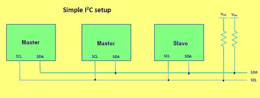 I2C is a ubiquitous serial protocol. It is a half-duplex, synchronous, multi-master, multi-slave, packet-switched, and single-ended. It is used to attach low-speed ICs to processors and microcontrollers in short-hall, intra-board communication. The most common voltages are 5 and 3.3 V. Besides the low voltages, total bus capacitance precludes transmission in excess of several meters. The I2C physical two-wire interface is comprised of bi-directional serial clock (SCL) and data (SDA) lines.
There are two roles available at each I2C node: master and slave. The master node is comprised of the clock and essential circuitry in a single chip. It initiates communication with the slaves. The slaves receive the clock pulses and respond accordingly. After a stop bit is sent, master and slave roles may be reversed. Any number of masters may co-exist.
Modes of operation include master transmit, master receive, slave transmit and slave receive. The master initiates the proceedings by sending a start bit followed by the seven-bit address of the intended slave recipient. This is followed by a bit specifying a write (0) or read (1) request. The slave acknowledges with an ACK bit. Master and slave then continue is their specified receive and transmit modes. Product documentation states the messages that a slave is permitted to answer.
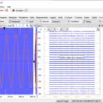
The typical way scopes display I2C bus signals is in a time-correlated scheme where both the actual bus signal displays in sync with its decoded interpretation into data and address bytes. Other display modes are possible, including a results table. This is a time-stamped display of bus activity set up to facilitate comparisons with software listings. In the Tektronix results table display, the user can also tap a line in the tabular display to make the scope automatically zooms in on the corresponding bus signals and resulting decoded bus waveform.
One key scope capability used for examining bus problems is the isolation and capture of specific events using the scope’s bus trigger. Bus triggering is a common feature of scopes used for all manner of serial bus examinations, not just for I2C. The user sets up the bus trigger so the oscilloscope will capture all of the input signals and one specified bus event will be positioned at the trigger point. For example, the scope might be set up to trigger on address 0x50 and data 0x00. It will than capture bus events coming after that event.
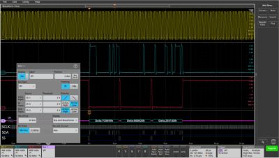
An SPI signal decoded on a Tektronix scope. Top is the SPI signal itself. At bottom is the scope’s interpretation of the SPI signal.
The Serial Peripheral Interface bus (SPI) was originally developed by Motorola for the 1980s-vintage 68000 series MCUs. It is now widely used in embedded system design primarily between MCUs and their immediate peripherals such as keyboards, displays, and memory chips.
The SPI bus is a master/slave, four-wire serial setup. The four signals are clock (SCLK), master output/slave input (MOSI), master input/slave output (MISO), and slave select (SS). Whenever two devices communicate, one is referred to as the “master” and the other as the “slave”. The master drives the serial clock. SPU is also a full-duplex protocol
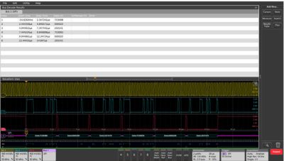
An example of a result table display, this one on a Tektronix scope. This time-stamped display of bus activity can be compared to software to find problems.
listings,
SPI devices don’t have unique addresses. Instead, SPI uses the SS line to specify the device transferring or receiving data. Thus each device on the bus needs its own SS signal from the master; three slave devices require three SS signals from the master. SPI can also be wired with slave devices daisy chained, each performing an operation in turn, and then sending the results back to the master (which can be used to verify the integrity of the data path).
Sometimes there’s no need for the slave to communicate back to the master, in which case the MISO signal may be left out altogether. In other cases there is only one master and one slave device and the SS signal is tied to ground. This setup is commonly called two-wire SPI.
In a SPI data transfer, an eight-bit data word shifts out on MOSI while a different eight-bit data word is shifted in on MISO. The effect is that of a 16-bit circular shift register. During a transfer, this 16-bit shift register is shifted eight positions, thus exchanging the eight-bit data between the master and slave. A pair of registers, clock polarity (CPOL) and clock phase (CPHA), determine the edges of the clock on which the data is driven. Each register has two possible states which allows for four possible combinations. A master/slave pair must use the same parameter values to communicate. If multiple slaves are used in different configurations, the master must reconfigure itself each time it must communicate with a different slave.
RS-232 was designed to connect data terminals to phone system modems and was devised in the 1960s. It is often used in embedded systems to support low data-rate communications between modules. RS-232 signals usually range from -13 to 13 V, although the actual specifications permit higher and lower levels. The low voltage signifies the idle line, a stop bit or logic 1. A high signal signifies a start bit or logic 0. Notice that this is the opposite to TTL.
The CAN bus started in the automotive industry and is still widely used there. But it’s simple two-wire design has been picked up by other industries such as industrial and building automation (see www.can-cia.org/). Scope packages that monitor CAN buses often include support for other buses frequently used in concert with CAN, including LIN and the higher data-rate version, CAN FD.
The Universal Serial Bus (USB) has replaced RS-232 in many applications. Computing platforms increasingly are moving to USB 3.1 interfaces, but embedded systems continue to use USB 2.0 for short-range (below 5 m) situations because it is economical and easy to implement. Many MCUs support the full-speed version handling data rates up to 12 Mb/sec. Some also support high-speed communication with data rates of up to 480 Mb/sec.
Finally, the Ethernet network standard has gone to higher-speed versions over time. It is common to find scopes with decode options available covering 10BASE-T and 100BASE-TX.

