• Skip to primary navigation
  • Skip to main content
  • Skip to primary sidebar
  • Skip to footer

Electrical Engineering News and Products

Electronics Engineering Resources, Articles, Forums, Tear Down Videos and Technical Electronics How-To's

  • Products / Components
    • Analog ICs
    • Connectors
    • Microcontrollers
    • Power Electronics
    • Sensors
    • Test and Measurement
    • Wire / Cable
  • Applications
    • Automotive/Transportation
    • Industrial
    • IoT
    • Medical
    • Telecommunications
    • Wearables
    • Wireless
  • Resources
    • DesignFast
    • Digital Issues
    • Engineering Week
    • Oscilloscope Product Finder
    • Podcasts
    • Webinars / Digital Events
    • White Papers
    • Women in Engineering
  • Videos
    • Teschler’s Teardown Videos
    • EE Videos and Interviews
  • Learning Center
    • EE Classrooms
    • Design Guides
      • WiFi & the IOT Design Guide
      • Microcontrollers Design Guide
      • State of the Art Inductors Design Guide
    • FAQs
    • Ebooks / Tech Tips
  • EE Forums
    • EDABoard.com
    • Electro-Tech-Online.com
  • 5G

Transient Voltage Suppressor Diode: What is it?

December 16, 2016 By Janet Heath

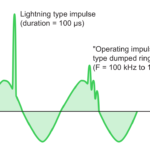
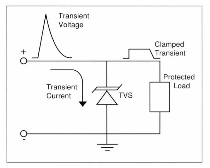
Transients are sudden high-frequency overvoltages that can destroy a chip. A silicon Transient Voltage Suppressor (TVS) is a circuit protection component that either attenuates (reduces) or filters a transient voltage spike (overvoltage), thus protecting your circuit. Another type of TVS diverts a voltage spike away from your circuit (also known as shunting, clamping, or bypassing.) TVSes protect circuits by utilizing the avalanche breakdown point of a silicon pn junction that’s created for this purpose. The pn junction returns to normal when the spike has passed and will clamp again on the next spike. In normal operation, the TVS is invisible to the circuit. A spike event that lasts a long time will necessitate the installation of a heat sink for the TVS, however. TVS devices are typically specified to handle in the range of kilowatts of peak power flowing through the TVS.

: Clamping a Lethal Transient to a Safe Level
Figure 1: Voltage on the Y-axis exceeds the upper limit of 20V and is instantly clamped to an acceptable lever by the TVS in the circuit. TVSs respond rapidly. (Image: MicroSemi MicroNotes 103)

TVS diodes (and TVS diode arrays) protect circuits from Electrostatic Discharge (ESD). A TVS can protect a signal chain either unidirectionally or bi-directionally. A bidirectional TVS is chosen when the protected signal is usually supposed to swing above and below ground, as in an AC voltage or a DC signal intended to operate at positive and negative voltages. A unidirectional TVS diode will only allow voltage either above or below ground (positive or negative voltage.)

TVSes are often used to protect inputs. A USB receptacle or port is an ideal case since ESD is often experienced at the input of a device: when someone walks across a carpet to plug in a USB cable, a charge can build up that causes electrostatic discharge at that input. The TVS takes the jolt and immediately clamps it, or cuts it off, before the maximum voltage that the USB chip can withstand is reached.

Figure 2: A TVS is invisible to the circuit it protects. Here, it diverts the overvoltage on the input to ground. (Image: MicroSemi MicroNotes 103)

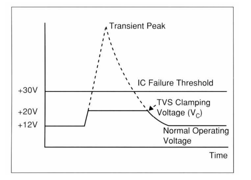
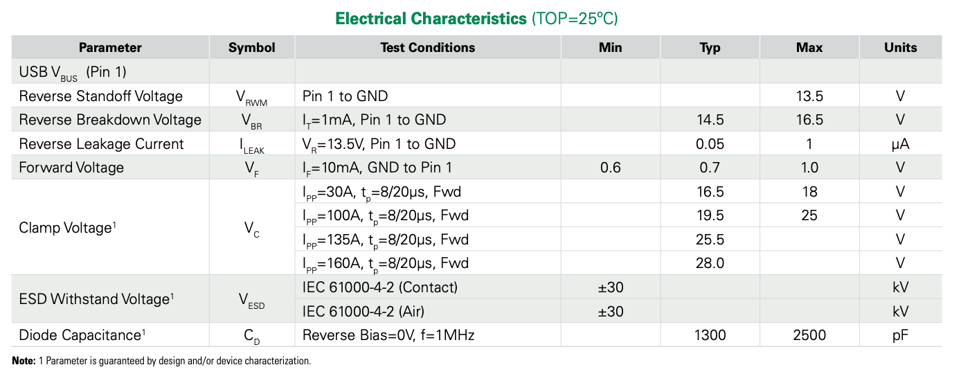
As for how to choose a TVS, make sure you know the maximum operating voltages for the devices in the protected circuit (load), as this will determine VWM, which is known in various datasheets as the working peak voltage, the maximum working voltage, the rated standoff voltage, reverse standoff voltage or maximum off-state voltage.  Littelfuse refers to VWM for a unidirectional TVS as “the maximum peak voltage that may be applied in the ‘blocking direction,’” if you expect to have no significant current flow. A bi-directional TVS is the same, except applies to both directions. The VWM is typically 10 – 15% below the breakdown voltage (VBR). VBR is the voltage where TVS devices go into avalanche. Temperature affects VBR level, so VWM is at least 10% below VBR, as VBR may creep lower as temperatures drop. A TVS should not have a breakdown voltage equal to the working peak voltage.

The clamping voltage (VC) is the highest voltage that is specified in a TVS and is usually greater than VBR by 35 – 40% and ~60% higher than VWM. Peak pulse power (PPP) dissipation is another rating that factors into safely suppressing various transients or surges. Since:

PPP = VC x IPP,

where IPP is the worst-case surge current that is expected. The IEC 6100-4-2 standard describes measurement techniques and testing for certification that includes ESD protection and may be a valuable reference to help determine IPP. Other standards, such as the Human Body Model, may also be good references.

If there are still several TVSes to choose from, choose the TVS with the lowest capacitance value, especially when using them with high-speed (high frequency) circuits.

Figure 3: Littelfuse’s SP1255 Series of TVS diode arrays protects the USB VBUs pin up to 160 amps. Capacitance and clamp voltages at varying currents are listed. (Image: Littelfuse SPA diode datasheet, SP1255 Series)

A TVS should also be physically placed near the input on the PCB.  Traces should be kept as short as possible to avoid parasitic capacitance.

You may also like:

  • EV charging
    Protecting fast EV charging stations

  • How to keep transients from disrupting low-power circuits

  • Don’t touch that! Things they don’t teach you in circuits…

  • Surge voltage protection considerations

  • Automotive load dump TVS – A unique transient voltage suppression…
DesignFast Banner version: 641873d7

Filed Under: FAQ, Featured Tagged With: littelfuse, microsemi

Primary Sidebar

EE Training Center Classrooms

“ee

“ee

“ee

“ee

“ee

“ee

Featured Resources

  • EE World Online Learning Center
  • CUI Devices – CUI Insights Blog
  • EE Classroom: Power Delivery
  • EE Classroom: Building Automation
  • EE Classroom: Aerospace & Defense
  • EE Classroom: Grid Infrastructure
Search Millions of Parts from Thousands of Suppliers.

Search Now!
design fast globle

R&D World Podcasts

R&D 100 Episode 7
See More >

Current Digital Issue

February 2022 Special Edition: Power Electronics Handbook

Up in the sky! It’s a bird! It’s a plane! It’s a flying battery! According to a company called Joby Aviation, in a few years you’ll be able to summon up an air taxi on your Uber phone app for trips of 25 miles or so. And you won’t have to feel guilty about the…

Digital Edition Back Issues

Sponsored Content

Positioning in 5G NR – A look at the technology and related test aspects

Radar, NFC, UV Sensors, and Weather Kits are Some of the New RAKwireless Products for IoT

5G Connectors: Enabling the global 5G vision

Control EMI with I-PEX ZenShield™ Connectors

Speed-up time-to-tapeout with the Aprisa digital place-and-route system and Solido Characterization Suite

Siemens Analogue IC Design Simulation Flow

More Sponsored Content >>

RSS Current EDABoard.com discussions

  • I am Alec, a new member!
  • electrode-skin impedance mismatch
  • how to estimate Senseamp offset voltage to use montecarlo ?
  • Weird transformer result in ads
  • could calibre lvs do not check mosfet B term

RSS Current Electro-Tech-Online.com Discussions

  • Relaxation oscillator with neon or...
  • High component count for long delay circuit (inrush resistor switch out)
  • DIY Mini 12v Router UPS malfunction
  • MOSFET gets hot and burns
  • Positive and negative sides of voltage source

Oscilloscopes Product Finder

Footer

EE World Online

EE WORLD ONLINE NETWORK

  • 5G Technology World
  • Analog IC Tips
  • Battery Power Tips
  • Connector Tips
  • DesignFast
  • EDABoard Forums
  • Electro-Tech-Online Forums
  • Engineer's Garage
  • Microcontroller Tips
  • Power Electronic Tips
  • Sensor Tips
  • Test and Measurement Tips
  • Wire & Cable Tips

EE WORLD ONLINE

  • Subscribe to our newsletter
  • Lee's teardown videos
  • Advertise with us
  • Contact us
  • About Us
Follow us on TwitterAdd us on FacebookConnect with us on LinkedIn Follow us on YouTube Add us on Instagram

Copyright © 2022 · WTWH Media LLC and its licensors. All rights reserved.
The material on this site may not be reproduced, distributed, transmitted, cached or otherwise used, except with the prior written permission of WTWH Media.

Privacy Policy