User expectations are calling for faster computers and handheld devices. Keeping these faster processors operating efficiently required lowering supply voltages. So, where in the past, 5 V supply buses operated with ±5 percent tolerance today’s low voltage processors require a much smaller tolerances on the order of ±1 percent. So, a 1.1 V bus has a tolerance of ±11 mV. This has required a reformulation of the testing methods for power distribution networks (PDN) to ensure power supply integrity.
PDNs are common to any devices needing power and noise, crosstalk, or load change transients on power rails propagate throughout the system. These spurious signals can cause a host of other problems like timing jitter. Therefore, it is important to measure and evaluate not only the DC voltage but also noise, ripple, and crosstalk on a power rail.
This requires looking at signals with a range of millivolts on power rails with DC levels of 1 volt or greater. Therein lies the problem. A typical oscilloscope set to its 5 mV range can only compensate of an offset of ±300 mV. This means that even a 1 voltage power bus appears off the screen. Of course, using a higher vertical sensitivity, like 200 mV, increases the offset range to ±3 V but the noise and ripple, assuming it is less than the voltage tolerance or 11 mV, is almost invisible. This is where the power rail probe comes into play.
Power rail probes, which are offered by all four major oscilloscope providers, attack this problem in several ways. First, they offer attenuation ranges that are close to 1:1 so as not to attenuate these already small target signals.
Next, they prevent power loading by splitting the signal path into DC and AC paths as shown in Figure 1.
The DC path offers a DC resistance of 50 kΩ. The AC path, capacitively couples the signal. The DC path has a low pass frequency response. The AC path has a high pass response. The paths are summed at the probe output and operate into the oscilloscope’s 50 Ω input termination yielding a flat frequency response. Operating into the 50 Ω scope input offers the lowest noise contribution and highest bandwidth from the oscilloscope. Bandwidths of these probes vary from 1 to 6 GHz depending on the model chosen. Finally, the rail probes provide a very wide, high-precision, offset voltage, typically in the range from ±15 to ±60 V.
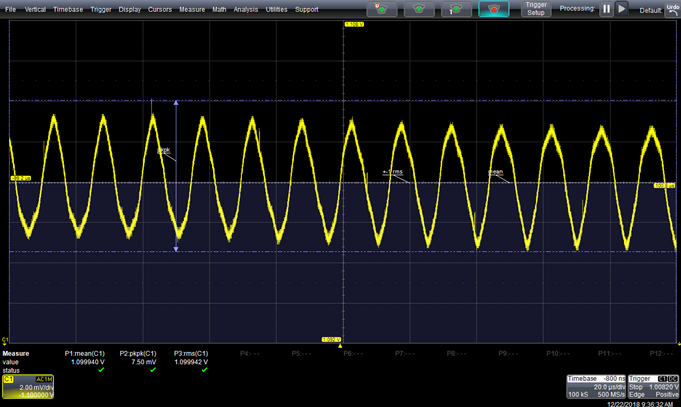
Let’s look at a typical measurement. Figure 2 shows a measurement of periodic and random deviation (PARD) on a 1.1 V bus. PARD is an industry-wide term that measures the deviation of the instantaneous bus voltage from its average or mean value. In the figure, the peak-to-peak measurement parameter reads the PARD values as 7.5 mV. This includes periodic, random, and some narrow spike components. PARD does not include slow variations in the bus voltage below 20 Hz which is referred to as drift. The rail probe provides the offset, read in the figure as -1.1 V in the C1 annotation box. The rail probe used in this example has an offset range of ± 30 V. This allows the signal to be measured using the 2 mV per division vertical scale which has a ±300 mV range without the probe.
Power rail probes also include several interconnection accessories. All suppliers provide a browser for manual probing on circuit boards and a solder-in cable. The solder-in cable provides the highest bandwidth, and the browser provides the lowest bandwidth. Some suppliers also supply cables that connect the probe to ultra-miniature, Snap-On coaxial connector receptacles designed into the circuit board. The bandwidth is also dependent on the type of connector used.
Power rail probes are offered by four major oscilloscope suppliers, and Table 1 summarizes those offerings.
|
Supplier/Model |
Maximum Bandwidth |
Offset Range |
Dynamic Range |
Attenuation |
DC Impedance |
AC Impedance |
Connectivity Options |
|
Keysight N7020A N7024A |
2 GHz 6 GHz |
±24 V ±15.25 V |
±850 mV ±600 mV |
1.1:1 1.3:1 |
50 kΩ 50 kΩ |
50 Ω
|
Browser Solder-in |
|
Rohde & Schwarz RT-ZPR20 RT-ZPR40 |
2 GHz 3.5/4 (typ) GHz |
±60 V ±60 V |
±850 mV ±850 mV |
1:1 1:1 |
50 kΩ 50 kΩ |
50 Ω 50 Ω |
Browser Solder-in |
|
Tektronix TPR1000 TPR4000 |
1 GHz 4 GHz |
±60 V ±60 V |
±1 V ±1 V |
1.35:1 1.35:1 |
50 kΩ 50 kΩ |
50 Ω 50 Ω |
Browser Snap-on Solder-in |
|
Teledyne LeCroy RP4030 |
4 GHz |
±30 V |
±800 mV |
1.2:1 |
50 kΩ |
50 Ω |
Browser Snap-on Solder-in |
Table 1: Summary of available power rail probes.
Power integrity measurements definitely benefit from the use of the power rail probes. These probes eliminate the loss of dynamic range that usually happens when a small voltage has to be measured on a much higher DC voltage.
