Part 1 of this feature looked at the people, project, and the vessels of the first trans-Atlantic cable project. Part 2 looks at the cable, test and repair, and implications of the final success.
The cable
Managing the cable and rolling it out smoothly with the proper tension so it would not snap with the ship’s motion and ocean swells was another problem to be solved. The first attempts had a manually operated tensioner where a crewman read a tension gauge and controlled a brake as needed. However, the complexity and size of the undertaking, along with the ocean swells, made this unreliable, leading to cable breaks followed by retrieval attempts and splicing. The successful attempt made use of a radical design, which was not only smaller and lighter than predecessors but also had a more accurate way of measuring tension in real time and automatically adjusting a controlling brake.
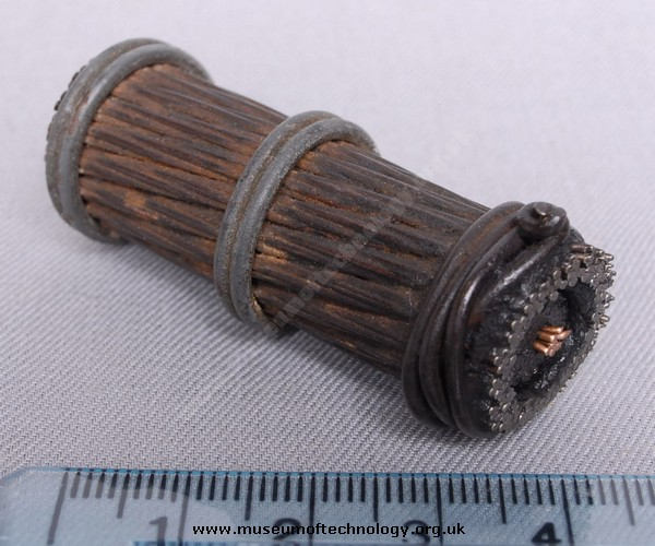
The cable for the first attempt was made of seven strands of copper wire (each 0.028 inches in diameter) twisted to make a core 0.083 inch in diameter. This core, which weighed about 100 pounds per nautical mile, was covered with three separate layers of processed gutta-percha, a latex-like secretion from tropical trees (the project consumed nearly the entire worldwide production of gutta-percha). This, in turn, was covered by hemp saturated with a mix of tar, pitch and linseed oil.
The electrical core was protected by an armored layer of 18 iron wires, each made of seven strands. The entire cable was covered with another layer of tar. The final cable measured about 5/8-inch in diameter weighed about one ton per nautical mile (20 times the core itself) and had a tensile strength of about 6,500 pounds. Due to the limited understanding of metallurgy, the cable’s conductivity was inconsistent and ranged over more than a two-to-one ratio.
With each successive submarine attempt, the cable was improved and strengthened. The cable carried by the Great Eastern on the successful run used the same type of copper core with seven strands but was three times heavier overall. The copper used was more highly refined and purified to ensure good and consistent conductivity. The three layers of gutta-percha were increased to four and supplemented with an intermediate layer of an insulating compound developed specifically for the project.
The iron cladding also was upgraded to a newly developed form of steel called charcoal iron. More pitch-soaked hemp also was used, and the cladding was galvanized to inhibit rust and corrosion. This cladding, in particular, had an additional benefit: the outermost hemp layer did not have to be impregnated with pitch to resist corrosion. This meant the cable was no longer sticky and thus did not attract and hold tiny bits of metal, which caused problems. Techniques were developed to test the electrical and insulation integrity of the cable as it was being spooled out so that defective sections would not be used.
The final cable weighed about twice as much as the one used on the first attempt and was twice as strong (Figure 1). However, despite its larger overall diameter (1.1 inches), it was less dense and therefore lighter in water. This apparent lightness, in turn, reduced the load on the above-surface cable as it was spooled out.
Test and repair
“Electronics” as we know it today did not exist in the 19th century; it was still a world of passive circuits until the invention of the amplifying triode in the early 20th century. Any signal sent down a cable had to arrive and be sensed at the far end without benefit of repeaters or boosters. The only way to test the cable’s integrity both at manufacturing and after its underwater placement was to send a pulse down the cable and look for a minuscule output at the far end.
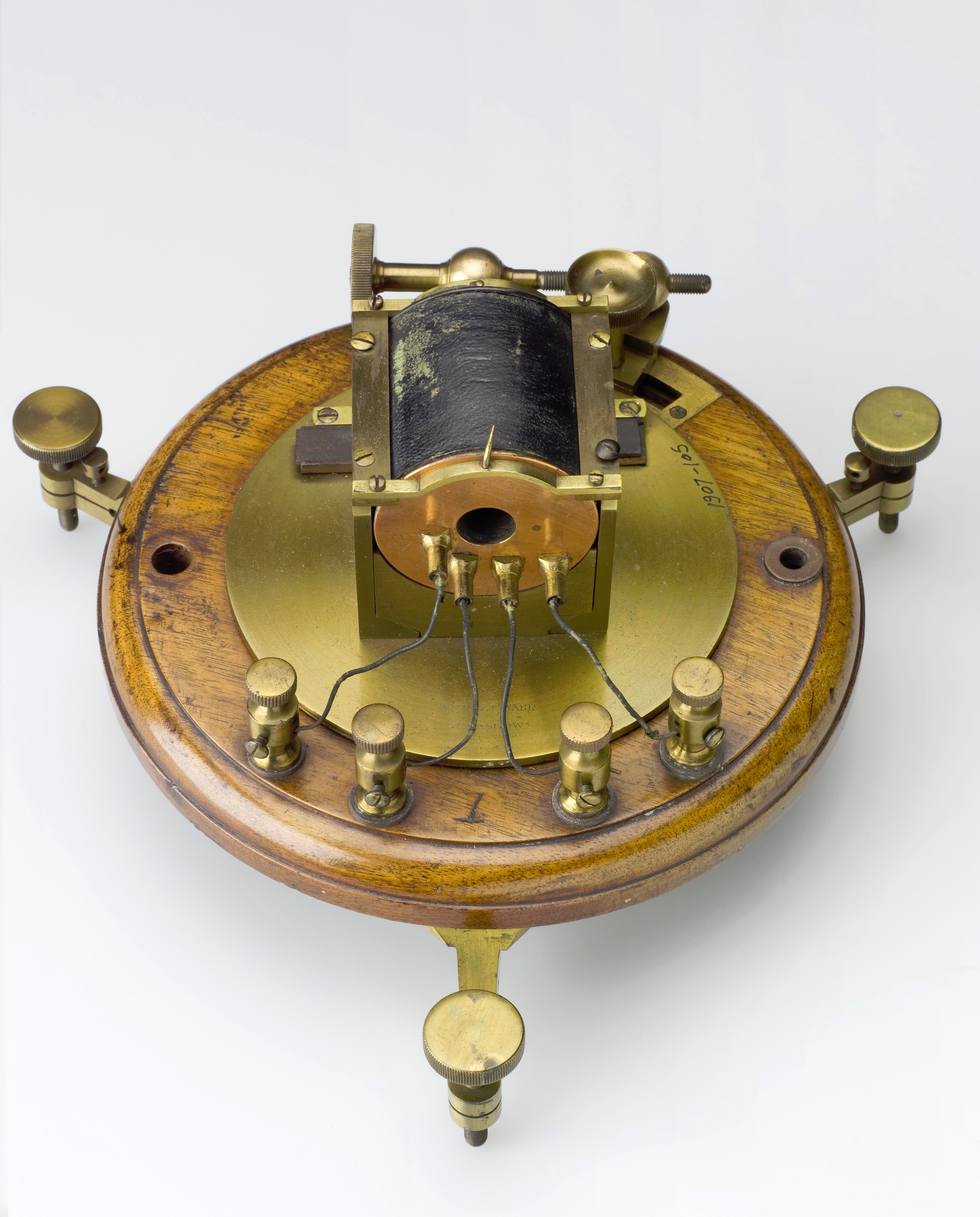
This is where Lord Kelvin played a role. In addition to advising on the cable construction and electrical aspects, he developed a highly sensitive galvanometer that would visibly indicate if even a tiny current flow existed and, thus, an intact cable (versions of this device are still in use). Lord Kelvin wound an electromagnetic coil around a lightweight core, to which he attached a mirror (Figure 2). By shining a beam of on this mirror, any minuscule deflection due to current flow could be seen via a movement of the reflected beam.
Repairing the cable meant that the break first had to be found. Today, time-domain reflectometry (TDR) is routinely used to locate cable breaks with high accuracy and precision. For breaks of the first transatlantic cable, however, the cable-laying ship stumbled around blindly; crews used a grappling hook that was dragged along the ocean floor in an effort to snag the cable then bring it to the surface for splicing. The splicing itself was a major project requiring special fixtures, onboard welding, skilled labor and re-insulating over the splice. All of this done had to be done on a rolling ship.
For invisible breaks of the copper conductor within the cable, sections were pulled up from the seafloor, sliced off a piece at a time until the break was located and then re-spliced. Special grappling and lifting techniques, using a helper ship and an intermediate subsurface buoy, were developed so the weight of the cable being hauled on board did not snap the onboard cable.
On one attempt to locate a break, the chief electrical engineer sought to boost signal strength by increasing the voltage supplied by batteries via induction coils to several thousand volts from the nominal level of several hundred volts. This may have burned out the cable and created many internal short circuits, which likely resulted in the failure of the overall attempt. Recognize, though, that our present technical understanding and consistent definitions of voltage, current, resistance and insulation breakdown, plus an electrical model of a cable, was non-existent at the time.
Success, then scrap
After the first successful connection, messages could be sent between North America and Europe without the need for physical transport by ship and associated time lags. However, the telegraph signaling rate was on the order of one character per minute due to the inherent series inductance and parallel capacitive loading within the cable, neither of which was well understood. The cost to transmit a message was an astonishing $1 per letter in an era when a workingman’s pay might be a few dollars per week.
The Great Eastern was celebrated as a man-made wonder, and it was. However, it was good at only one thing and was costly and complicated to operate. The ship was so large that there were only a few places for it to dock, and it needed a squadron of smaller ships to ferry supplies, crew, and fuel to it. It was soon replaced by smaller ships that used new techniques, and it was no longer viable. Suggestions were made to turn it into an ocean liner, or to hollow it out and use it as a floating drydock; after a few decades of passing from one owner to another, it was sold for scrap.
Implications of the success
The successful deployment of this first transatlantic submarine did more than provide a way for news and diplomatic messages to reach the other side with a speed which was orders of magnitude faster and with greater reliability than even the best alternative (although we may consider it pathetically slow). Like many such projects, it relied on the latest in technology, but also spurred advances that other projects soon leveraged. These advances included material science and metallurgy, large-scale manufacturing, ocean-going operations, large-vessel design and construction, principles of cable-based media, and testing and repair techniques.
Within a few years of this success, additional transatlantic cables were deployed and operated on parallel submarine routes. This added capacity and redundancy linked many far-flung locales. For example, at the time of the historic volcanic explosion at Krakatoa in 1883 (which killed over 300,000 people), the Dutch trading post about 10 miles away was linked to nearby islands and in turn to Europe and North America so that news of the eruption reached those places within hours. The impact of this speed of news travel is something we probably can’t grasp.
Also recognize this project was conceived, funded, and executed by private group (admittedly with some technical help and modest financial support from the U.S. and British governments) They had to literally sink huge amounts of time, energy and money into such an audacious project, and not give up even after several costly and frustrating failures. (In some ways, this is analogous to the private satellite and manned space projects now underway.) They continued and re-started despite major risks, and at great cost. The References provide much more detail, drawings of the ship and efforts, as well as photos of the instruments used.
Related EE World Content
Optical amplifiers, Part 1: Applications and considerations
Optical amplifiers, Part 2: Basic implementations
GPS, Part 1: Basic principles
GPS, Part 2: Implementation
References
- John Steele Gordon, “A Thread Across the Ocean: The Heroic Story of the Transatlantic Cable,” Walker & Co, NY, 2002.
- Chester G. Hearn, “Circuits in the Sea: The Men, The Ships, and the Atlantic Cable,” Praeger Publishers, Westport Conn., 2004.
- “The Great Transatlantic Cable,” (video), PBS American Experience, 2005.
- The Trans-Atlantic Telegraph Cable: 150th Anniversary Celebration 1858-2008
- History Magazine, “The Transatlantic Cable”
- Submarine Cable Systems, “Submarine Cable System History: 150 Year History of Submarine Cables”
- Science Museum Group (UK), “Sending messages across the Atlantic”
- The Museum of Technology, The Great War and WWII, “Telegraphy”
- BT (formerly British Telecom), “Queen Victoria, the SS Great Eastern, 2500 miles of cable and a communications milestone”
- History of the Atlantic Cable & Undersea Communications
- Thomas C. Reed, “At the abyss : an insider’s history of the Cold War” (one chapter tells about highly classified undersea tapping of Russian cables by the U.S. Navy)
- Andrew Blum, “Tubes: A Journey to the Center of the Internet,” (very interesting look at the physical infrastructure of the Internet and how fiber-cables are brought ashore, terminated, and actually connected to the it)


Leave a Reply
You must be logged in to post a comment.