Power supplies and converters tend to be simple in principle, yet their actual design – including overcoming the subtle issues which degrade and impede their performance – is the real challenge. In Part 1, we looked at the flyback design and some distinct advantages along with unique idiosyncrasies. This FAQ looks at some of these advanced points for flyback designs.
Q: The flyback design sounds simple; is that all there is to the flyback approach?
A: As with all power-supply and converter designs, the answer is absolutely not: “the devil is in the details.” There are many subtleties in improving performance and efficiency which complicate the initially simple functioning. Among the two associated with flybacks (and other converter types, as well) are:
- discontinuous conduction mode (DCM) (Figure ), where the transformer is allowed to demagnetize during each switching cycle completely; usually, this is done with a fixed switching frequency and modulation of the peak current to meet the load requirements.
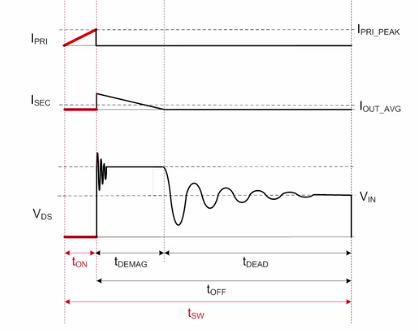
Fig 1: In the discontinuous conduction mode, the transformer is completely demagnetized during each switching cycle. (Image: Texas Instruments)
- continuous conduction mode (CCM) refers to an arrangement where current is always flowing in the transformer during each switching cycle, and therefore some residual energy is always present in the transformer because each switching cycle begins before the current is completely depleted (Figure 2).
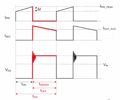
Fig 2: In continuous conduction mode there is always some flow of current in the transformer, and some residual energy is always present in its inductive aspects. (Image: Texas Instruments)
Q: What are the relative attributes of DCM versus CCM?
With DCM, there are no reverse-recovery losses in the output rectifier since its current goes down to zero during every switching cycle. Also, the required primary-side inductance value is low and thus can be satisfied with a smaller transformer. Finally, the DCM design is inherently more stable, because there is no zero in the right-half-plane zero of its transfer function.
DCM flybacks have the disadvantage of very large ripple currents, which may require large EMI filters. Fixed-frequency DCM flybacks have higher losses because they can turn off the MOSFET switch when its drain to source voltage may be relatively high.
In contrast, CCM has small ripple and RMS currents; these lower currents also lower the conduction and turn-off losses, while lower peak currents allow for smaller filter components.
On the negative side, CCM designs have a zero in the right-half-plane of their transfer function, which will limit the bandwidth of the control loop and its dynamic response. CCM flybacks also require a larger inductance and thus a larger magnetic component.
Q: There are also terms such as quasi-resonant operation and valley switching — what are these?
A: This is where the additional subtleties of flyback (and some other) supply topologies start to appear. In DCM, there is a delay before the primary side switch turns on again to start the next switching cycle, during which time neither the diode nor the MOSFET is conducting; this is called dead-time or resonant time. In this dead-time period, an LC resonant “ring” is created by the interaction between the primary inductance of the transformer and the parasitic capacitance at the switch node.
A quasi-resonant (QR) control design adjusts the peak current and switching frequency, so the MOSFET turns on at the first “valley” of this resonant ringing so that the flyback converter will have minimized losses (Figure 3).
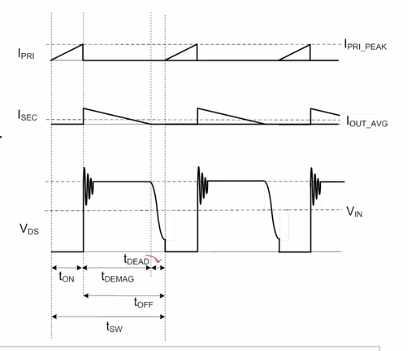
Fig 3: A quasi-resonant control design minimizes losses by adjusting the peak current and switching frequency, so the MOSFET turns on at the first “valley” of this resonant ringing. (Image: Texas Instruments)
Valley switching is related to QR operation and is a subclass of DCM, where the controller detects when the dead-time resonant ring is at its low point (Figure 4). It then turns the MOSFET on at this point to start the next switching cycle, with the result of minimizing switching losses.
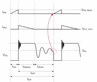
Fig 4: In valley switching technique of QR operation, the controller detects and turns on the MOSFET when the dead-time resonant ring is at its low point to minimize switching losses. (Image: Texas Instruments)
Q: What started out as a simple converter topology seems to have evolved to a much more complicated one. How can a flyback design be implemented without so many issues?
A: This is the reality of nearly every power-supply converter design. They start simple but getting from “good” to “really good” involves juggling multiple goals of high efficiency, tight regulation, low ripple, and more is difficult. There are “add-ons,” and subtle enhancements to a basic design which make the difference, while eking out those few extra percentage points in performance takes considerable extra effort. Fortunately, skilled power converter experts have devised ways to do this by adding a few extra components, and by leveraging the unique capabilities which ICs offer as controllers.
As a result of using these IC controllers which remove much of the burden of both basic and enhanced flyback operation, very good designs are within reach of most engineers
Q: Can you give some examples?
A: Let’\s take a brief look at flyback-controller ICs from three leading vendors, each with significant experience in design of controller ICs for power converters as well as complete converters:
- The Analog Devices LT8304, a transformer-Isolated flyback converter with integral 150 V/2 A switch. It accepts an input voltage between 3 V and 100 V, and the output voltage is programmed with two external resistors and a third optional temperature compensation resistor. The schematic of Figure 5 shows it in a circuit which takes a 4 V to 28 VDC input and provides a 1000 V/15 mA output.
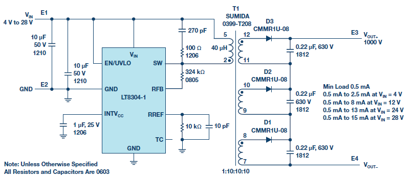
Fig 5: This transformer-isolated flyback design uses the Analog Devices LT3618 to regulate a 54 VDC output from a 20 VDC TO 600 VDC source. (Image: Analog Devices)
This design uses a transformer with three split-output windings on the secondary side, where the primary-side to secondary-side turn ratio is 1:10:10:10, instead of a single-secondary winding 1:30 transformer. The use of this 1:10:10:10 transformer enables the output voltage stress to be split among three high-voltage output diodes and three high-voltage output capacitors. Thus, the individual component voltage ratings need only be one-third of the total voltage, which allows more options for output diode and output-capacitor selection.
- The Texas Instruments UCC28780 (Figure 6), an optocoupler-based flyback controller that complies with stringent global efficiency standards such as DoE Level VI and EU CoC V5 Tier-2; its performance to be tailored to both silicon and gallium nitride power FETs.

Fig 6: Using an optocoupler for isolation, this design center on the Texas Instruments UCC28780 controller provides 20 V at up to 2.25 A from a 115/230 VAC line source. (Image: Texas Instruments)
- The MAX1856 from Maxim Integrated (Figure 7), a transformer-based flyback converter. Using a 12 VDC input and a transformer with multiple secondary windings, it develops both -24 VDC and -80 VDC for landline subscriber line interface circuits (SLIC) power supplies of “plain old telephone service” (POTS); the -24 V is for the loop service while the -80 V is for the ringer.
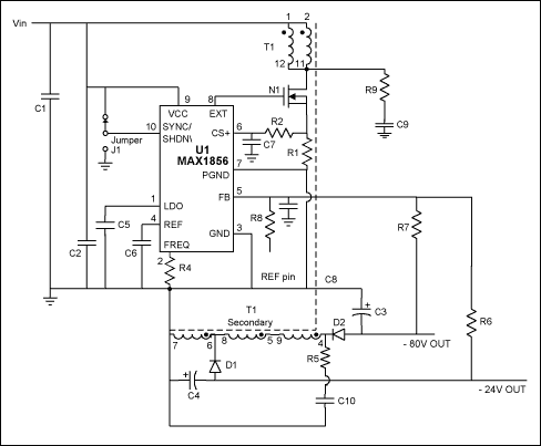
Fig 7: This flyback design using the Maxim MAX1856 is designed for landline telephone systems; it produces both -14 VDC and -80 VDC outputs from a +12 VDC supply. (Image: Maxim Integrated)
When selecting a power supply/converter topology, there are many legitimate possibilities to consider, each with a unique set of features as well as positive and negative characteristics. These must be weighed against the system priorities and their technical performance and dollar costs. The flyback approach is a viable contender in applications under several hundred watts at voltages from single digits to kilovolts, and it is especially attractive when multiple DC output and input/output isolation are required.
EE World Online References
Optocouplers, Part 1: Principles and usefulness
Optocouplers, Part 2: Parameters and applications
Power-supply noise, Part 1
Power-Supply noise, Part 2
Working with higher voltages, Part 1: Voltage boosters
Working with higher voltages, Part 2: Voltage multipliers
Other References
Electrical Engineering Stack Exchange, “How does a CRT television flyback really operate”
Autodesk Instructables, “2n3055 Flyback Transformer Driver for Beginners”
Robert Gawron, “High voltage supply (10-30kV) made from CRT television flyback transformer”
Electronic Repair Guide, “What Is Flyback Transformer?
Texas Instruments, “Understanding the Basics of a Flyback Converter”
Analog Devices, “1000 V Output, No-Opto, Isolated Flyback Converter”
Maxim Integrated, Application Note 1166, “Flyback Transformer Design for MAX1856 SLIC Power Supplies”

Leave a Reply
You must be logged in to post a comment.