The world is full of MOSFETs — they are the cornerstone of most ICs. However, the humble JFET still exists, although it is a bit of a niche market now and not always easy to find. Vishay, who took over the Siliconix brand many years ago, seem to have dropped JFETs now, although Siliconix was one of the major manufacturers of JFETs in the past. They are still listed as active but “non-stock” at places like Digikey but absent from Vishay’s website.
So, who still makes them and are they worth hunting out? The key characteristic of a JFET is low noise and very high input resistance. This made them the ideal choice for certain types of amplifiers, such as charge amplifiers, as well as the front end of low noise opamps. However, CMOS has improved so much that a modern CMOS opamp can beat an old JFET one. Also, modern CMOS chopper amplifiers can eliminate the problem of 1/f noise – an area where JFETs can also be very good, but JFETs cannot eliminate 1/f noise altogether. JFETs also usually have very low current noise — essential for high-impedance, low-noise circuits.
ON Semiconductor still make a few, as do NXP, although they are fairly well hidden on their website. Many of the devices that you will come across are very old ones such as the J201 which has been around for over 30 years. You will come across surface mount versions of quite a few of the old devices. Linear Systems make a few devices – mostly alternatives to old ones such as the LSK170 which is an alternative to the obsolete Toshiba 2SK170. Central Semiconductor also makes a few alternatives to old JFETs. InterFET makes a few unique devices with particularly low noise rather than just making duplicates of old devices.
It is probably best to illustrate the benefits of JFETs with an example. Selecting a device is not that easy because selection guides leave a lot to be desired. For example, if you look on InterFET’s website and look under “Low noise amplifier”, you will find the 2N6451/2/3/4 which has a maximum noise voltage of 3nV/rtHz at 1kHz. Under “low noise audio” you will find the IFN860 which has a maximum noise of 2nV/rtHz at 1kHz but that is a dual device. To find the IF3601 you will need to look under “low noise high gain” which has a typical noise of 0.3nV/rtHz at 1kHz — no maximum figure is given. To find more information you need to look for the “process data” for the device you are interested in. That gives the noise at 10Hz for the IF3601 as around 0.4nV/rtHz at 1kHz which is remarkable. It probably achieves some of this low noise performance due to its sheer size — the die is nearly 1.9mm x 1.9mm. That brings with it the problem of input capacitance.
While the 2N6451 has 13pF of input capacitance (gate-source) the IF3601 has up to 650pF. These are taken from the process data graphs for Vgs=0V. So, while input resistance may be high, the capacitance may limit your bandwidth if your source impedance is also high.
It is worthwhile looking up the characteristics of a JFET to better understand their use. I will just look at the common source amplifier with some variations. A JFET is a depletion mode device whereas MOSFETs are usually enhancement mode. This term is a little confusing as both devices will increase the drain/source current with increasing gate voltage (for an N-channel device). The difference is that an enhancement mode device will have zero current with zero gate-source voltage whereas a depletion mode device will have a high current at zero gate-source voltage. A JFET is therefore normally used with some negative bias to the gate-source to reduce the current and operate the device in the linear region. It cannot have a positive voltage applied to the gate-source because that will start to forward bias the junction.
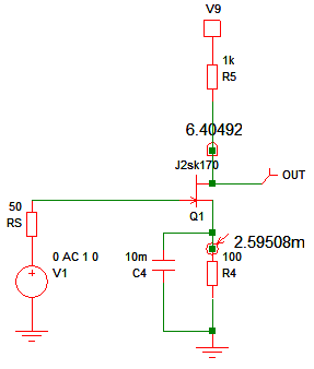
So, a simple common source amplifier would look something like this.
The gain and noise will look like this.

The benefits of a large area device such as the IF3601 are the considerably lower 1/f noise as shown below. Midband noise is also lower, and would be lower still if it wasn’t for the 50-ohm signal source resistance used.
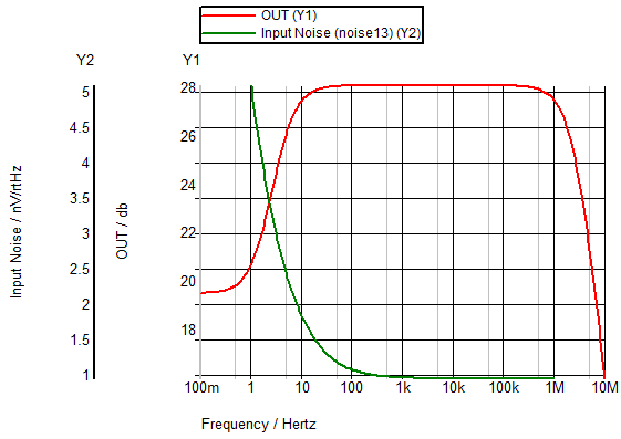
When you start achieving amplifier noise down to just a couple of nV/rtHz you need to take care with every resistance in the circuit because 50 ohms has a noise of 0.9nV/rtHz so to make effective use of a transistor with 0.3nV/rtHz you need a lot lower signal source resistance.
The disadvantage of the high input capacitance and Miller capacitance of the IF3601 circuit shown can easily be seen in the frequency plots. The IF3601 has a lot lower bandwidth compared to the 2SK170. The low-frequency bandwidth is also affected because the IF3601 will have a lower source resistor and so needs even higher capacitance to decouple it. However, the effects of higher current on noise are small so the IF3601 could be operated at a lower current with a higher source resistor.
Cascode circuits are one way of reducing the Miller capacitance effect, as discussed in an earlier blog, but those of you who rushed out and bought the third edition of The Art of Electronics after my earlier blog could have a look at the circuit in figure 3.34 of the book – shown below.

As well as reducing the effect of Miller capacitance without a cascode, it makes it easier to have a very low-frequency bandwidth without needing a huge capacitor.
If you aren’t sure how good some of these noise figures are, compare with the best opamps you can find such as the AD797 from Analog Devices at 0.9nV/rtHz at 1kHz or the LT1028 from Linear Technology (acquired by Analog Devices) at 0.85nV/rtHz. Also, you would need to input resistance/bias current and current noise. For example, the LT1028 has around 25nA of input bias current and noise current of several pA/rtHz. The AD797 has even higher bias current at 0.25µA or more. So, the JFET characteristics are pretty good by comparison provided you can design a circuit to use them to the full.