Free-space optical links provide a reliable, cost-effective, and quick way to link two fixed communication nodes located a few kilometers apart.
The previous part of this article looked at real-world issues that make a practical FSO link a design challenge. This part looks at a family of commercially available FSO systems.
Q: Can you build your own FSO link?
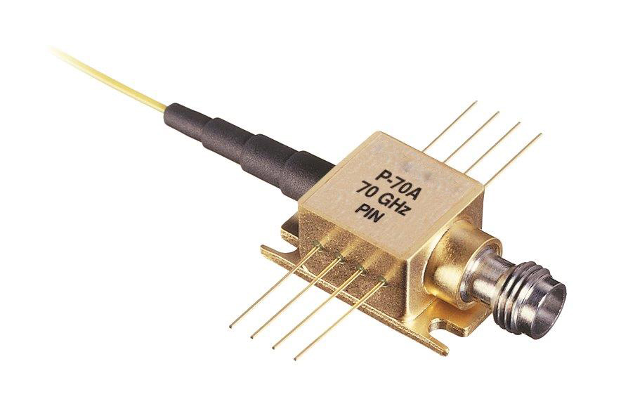
A: Yes and no. All the parts are standard off-the-shelf components such as the P-70A ultrafast, InGaAs PIN photodetector from MACOM (Figure 1.) This proprietary, back-illuminated semiconductor diode design optimizes speed, sensitivity, and low polarization dependence for both 1310 nm and 1550 nm wavelengths. The detector is mounted in a compact 8-pin butterfly-style package.
Q: So why do you also say “no?”
A: An FSO link is a complicated integration of electronics, electro-optical components, lenses, mechanical design, and more. Given the speed at which it operates, and its electronic and optical nature, everything has to be electrically, mechanically, and optically precise, stable, and consistent. Further, testing such a system is a significant task.
Q: What’s the alternative?
A: FSO link systems are available from over a dozen manufacturers, with some broad-application models and others more tightly focused on application niches. We’ll look at the Canon Canobeam family due to its popularity, longer history, spread of models and features.
Q: What’s an overview of this Canobeam family?
A: The first unit, the Canobeam 1, was introduced in 1993 and then expanded to become the broader Canobeam DT-100 family with faster systems, smaller ones, and ones with additional user-side interfaces and system features (Figure 2). A DT-100 for one node (you’ll need two) costs between $20,000 and $50,000.
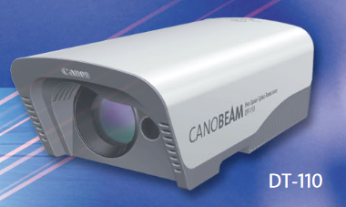
Q: What are the basic performance specifications for these units?
A: The DT-110 and DT-120 support 25 Mbps to 156 Mbps links at distances up to 0.5 km and 1 km (typical) respectively and twice that under favorable conditions. The DT-130 is for links up to 1.25 Gbps and 1 km nominal.
Q: What about size and power?
A: All units in the family are in the same-size enclosure measuring about 50 cm front-to-back, 25 cm wide, and 17 cm high. The units weigh about 8 kg and require just 20 W from a standard AC line (48 V power is also an option).
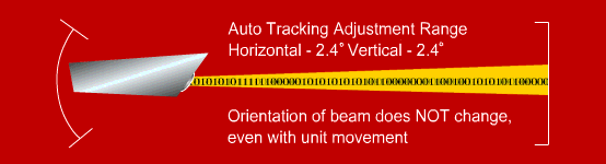
Q: Is there a special feature in these units?
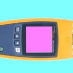
A: Yes, all units in the Canobeam family come with an autotracking function – a form of adaptive optics – that adjusts the laser-beam axis to compensate for slight movements in the building or installation base due to temperature variations or vibration due to wind and other factors (Figure 3). An internal processor calculates the point of maximum light input and controls the laser axis as needed.
Q: Are there any other features of interest?
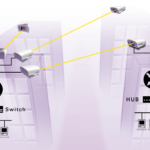
A: Yes, units in this family (and most units from other vendors) can be “daisy-chained” in repeater mode for longer distances. In other words, site A links to site B via FSO, where two units are installed and connected. The second unit at site B then links via FSO to a unit at site C.
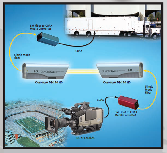
Q: What is an example of a quick set-up-and-go application in contrast to fixed installation?
A: FSO systems can be used to cover live news or sports events, where the mobile video camera link to one FSO whose beam crosses over city streets, parking lots, and traffic to another FSO, which in turn connects to the mobile studio van (Figure 4).
Conclusion
Terrestrial free-space optical links are alternatives to optical fiber or RF links for high-speed data interconnection over moderate distances. This approach offers convenience, reliability, ease of setup and use, and other advantages. The hardware and installation costs make them a viable option in many limited-range situations. They have issues with path interference due to various external factors, and these have been carefully studied and analyzed to optimize system performance.
Related EE World Content
Is Li-Fi “To Be” or “Not To Be”? Part 3 – Status
Calgary signs on for Terabeam FSO gear
LightPointe receives FSO patent
References
- Wikipedia, “Free-space optical communication”
- Science Direct, “Free-Space Optical Communication”
- IEEE, “A Survey of Free Space Optics (FSO) Communication Systems, Links, and Networks”
- Stanford University, “Free-Space Optical Communications — References”
- Purdue University, “Designing A Free-Space Optical/Wireless Link”
- Macom, “Free-space Optical Communication”
- Intech Open, “Free Space Optical Communications — Theory and Practices”
- European Scientific Journal, “Free Space Optical Communications: An Overview”
- RTU/Kota, “Seminar Report on Free Space optic”
- Arvix, “Free Space Optical Communication: Challenges and Mitigation Techniques”
- Military & Aerospace Electronics, “Navy looks for companies able to build optical communications between aircraft and submarines”
- Proceedings of SPIE “Research in Free Space Optical Data Transfer at the U. S. Naval Research Laboratory”
- StartUs Insights, “4 Top Free Space Optics Startups Impacting The Telecom Industry”
- Light Reading, “Is It Finally Time for Free-Space Optics to Shine?”
- Canon, “Canobeam DT-150”
- Canon, “Canobeam”
- CommConnect, “Free Space Optics”
- Airlinx, “Canobeam’s Auto Tracking Feature”
- fSONA, “SONAbeam FSO Systems”
- FSona, “FSO Guide”