A “voltage reference” can mean anything from a simple resistive power supply rail splitter as a virtual ground for an opamp, to a high precision, low drift, low noise reference voltage for an analog to digital converter (ADC). For an opamp virtual ground, a couple of resistors and a capacitor can work and you may even be able to miss out the capacitor depending on the circuit design it is used with, but it has disadvantages.

If you load the generated mid rail point at all then it will move, so it isn’t very stable. A dynamic load which sources and sinks current from the midpoint will produce less variation if a capacitor is included, but it still won’t be stable. Also, the circuit always takes some current and depending on what current you need it to be able to supply, you could be wasting a lot of power all the time.
Texas Instruments created the TLE2426 rail splitter a while ago to improve on the resistive mid rail virtual ground. It simply buffers a resistive mid rail splitter. So, it only takes around 170µA but can sink or source 20mA when required. You could do the same thing with a couple of resistors and an opamp but you need to be careful of capacitive loads. Most opamps don’t like significant capacitive loads so if your circuit presents a capacitive load to the mid rail point then you could have instability. The TLE2426 is fairly tolerant of capacitive loads depending on the load current, as shown by this graph.

Resistive splitters are only as good as your supply voltage so will not be a true reference voltage. Your power supply may have a 2% tolerance and you must then add any new errors due to rail splitting. Also, noise could be a factor. Using a couple of low -value resistors, e.g. 10k ohms, is not actually too bad for noise at 9nV/rtHz compared to using the TLE2426 which has around 50nV/rtHz of noise, although that can be halved with the addition of an output capacitor.
For a true reference independent of the power supply you are more likely to be looking at shunt and series voltage references. A shunt reference behaves like a very good zener diode. A series reference is more like a voltage regulator. A voltage reference is usually based on a bandgap reference circuit, as are most voltage regulators. While you could use a zener diode, the output impedance can be 100 ohms or more depending on the zener voltage and current used.
A bandgap voltage reference works by combining the Vbe (base-emitter voltage) of a bipolar PN junction with the “thermal voltage” Vt = kT/q. Vbe has a temperature coefficient of -2mV/K at room temperature and Vt has +0.085mV/K. So, by multiplying Vt by around 23.5 and adding it to Vbe, you should get a zero temperature coefficient. As Vt is nominally 26mV at 300K and Vbe is 0.65V, you end up with a reference voltage of around 1.26V. The temperature coefficient still won’t quite be zero and in fact zero temperature coefficient is not necessarily at room temperature, but it is a good starting point for improved designs and explains why some voltage references have seemingly strange values such as 1.22V and 1.26V.
A shunt reference is used like a zener diode with a series resistor dropping the voltage from the power supply to the reference voltage. The Analog Devices ADR1581 is one example.

Depending on the current you want to take from the reference you need to make sure that the reference still has sufficient current through it to regulate correctly. For example, the ADR1581 requires 60µA to guarantee to work correctly, so if you want to drawn 100µA from the reference, you need to choose the series resistor so there is at least 160µA through the reference when there is no load. This can be wasteful of power. While 60µA is not much, if you wanted a peak current of 1mA from your reference then your circuit would be consuming 1.06mA all the time which is not great for battery operated equipment.
A series reference is more like a voltage regulator with a series pass transistor although it can have an opamp style push-pull output. The ADR291 from Analog Devices, for example, typically takes 9µA quiescent current but can supply 5mA at the reference voltage. Series references are therefore generally a lot better for battery-operatedBarc circuits than shunt references.
Another consideration for voltage references, particularly when used for ADC or DAC circuits, is the noise. While the ADR291 is listed as “low noise”, the noise is 480nV/rtHz. Compare that with the ADR441 which is 48nV/rtHz. However, the price of the lower noise is 3mA quiescent current.
One thing to be careful of depending on your application is that series regulators often only source current – they do not sink current. So, an application that needs to source and sink current from the reference must use either a shunt reference or one that is designed to both source and sink current. The ADR441 is actually capable of both sourcing and sinking current, unlike the Texas Instruments LM4132 which can only source current as you can see from the LM4132 functional block diagram below.
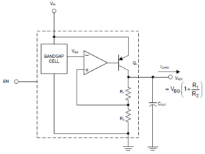
If you try to pull the LM4132 output above Vref then the only thing preventing it is the R1/R2 resistor divider. By contrast, the ADR441 block diagram below shows an opamp style output stage rather than a series pass transistor so can sink and source a significant current.

It is not always obvious which devices can only source current, particularly where no internal diagram is given. Also, some manufacturer’s selection tables don’t list source/sink current as separate options. The Analog Devices reference selection table lists both source and sink current which makes it easier to find one that can sink current.

Leave a Reply
You must be logged in to post a comment.