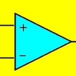
Operational amplifiers (op amps) and comparators have two inputs, inverting and noninverting, and an output that can usually swing from rail to rail and have the same schematic symbol. So, what’s the difference?
This FAQ compares the two devices and digs into some of the similarities and differences.
It begins with a top-level comparison of op amp and comparator operation, then looks at op amp classifications including voltage, current, transconductance, and transresistance designs, looks at op amp supply voltage topologies, considers various types of comparators like digital comparators, frequency comparators, current comparators, and window comparators and closes by considering how op amps can be used as comparators.
The output of a comparator is a logic signal that indicates which of the inputs is at a higher potential. Comparators are designed to be used as open-loop systems. They drive logic circuits, work at high speed, and can be overdriven. Op amps have analog outputs that are usually between the values of the supply rails and can get close to the value of the supply rails. They are designed for closed-loop applications with feedback from the output to the inverting input. Op amps amplify the voltage differential between the inputs and are used in signal chain, power conversion, and control applications.
Op amp classifications
There are four types of op amps:
- Voltage op amps take voltage in and produce a voltage at the output. Also called voltage feedback amplifiers (VFAs), these op amps can have an output potential relative to ground that is as much as 100,000 times or as large as the potential difference between the inputs.
- Current op amps take current in and produce a current at the output. Also called current feedback amplifiers (CFAs), the inverting input is sensitive to current levels.
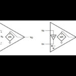
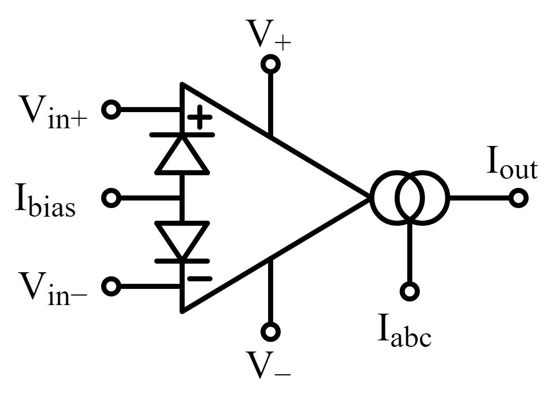
- Transconductance op amps (OTA, for operational transconductance amplifier), also called a voltage-controlled current source (VCCS), or a current to voltage converter, convert a voltage input to a current output. OTAs have a high impedance differential input and can be used with negative or without feedback in ‘open loop’ linear applications. They usually have an additional input to control the transconductance and can have a different schematic symbol than standard voltage op amps (Figure 1).
- Transresistance op amps convert a current input into a voltage output. They are also called transimpedance op amps or current controlled voltage sources (CCVSs). A feedback resistor controls the current to voltage gain. It’s useful in many sensor applications since it can maintain a constant voltage bias across the input source as the input current changes.
Op amp supply voltage topologies
Another way to classify op amp applications is by the supply voltage topology, like single supply versus dual supply versus rail-to-rail (Figure 2 below):
Single Supply – Most common op amp applications have inputs near 0 V and can operate using a single supply referenced to ground, so they are also called ground sense op amps.
Dual Supply – Typical op amp applications amplify signals close to, but not equal to, 0 V; however, when a 0 V input is required, VEE must be set to about -1.5V or less. That requires an additional power supply for the negative voltage. Hence this application is referred to as a dual supply op amp.
Rail-to-Rail – If VCC drops to close to 5 V, a single supply op amp can only handle inputs that are 1.5V less than VCC, potentially limiting performance. In applications that need maximum voltage swings, a rail-to-rail op amp can operate normally even if the input voltage swings between VEE and VCC. Since they can input/output over the full supply range, they are also referred to as input/output full swing op amps.

Comparator classifications
While comparators can be like op amps, they can also differ. Different types of op amps operate on various combinations of voltage and current inputs and outputs. Comparators can also operate on voltages and currents, but other types of comparators are available like:
Digital comparators, also called magnitude comparators, have two inputs that take digital numbers in binary form and determine if one number is greater than, less than, or equal to the other number. A basic form of the digital comparator is the XNOR gate since its output is “1” only if both input numbers are equal.
Frequency comparators can be designed with frequencies from the audio range up to hundreds of MHz, sometimes higher. A typical frequency comparator accepts two reference frequency inputs and a test frequency input which is compared to the references and produces ‘higher,’ ‘lower,’ and ‘same’ outputs depending on the relationship between the test frequency and the reference frequencies. Frequency comparators can be used for various applications, from audio and communications systems to monitoring shaft rotations in motors and wind turbines and timing devices.
Current comparators are current-mode signal processing circuits where the input is a differential current measurement, and the output is a digital signal. If the net current flow is into the circuit, the output is high; if the net current flow is out of the circuit, the output is low.
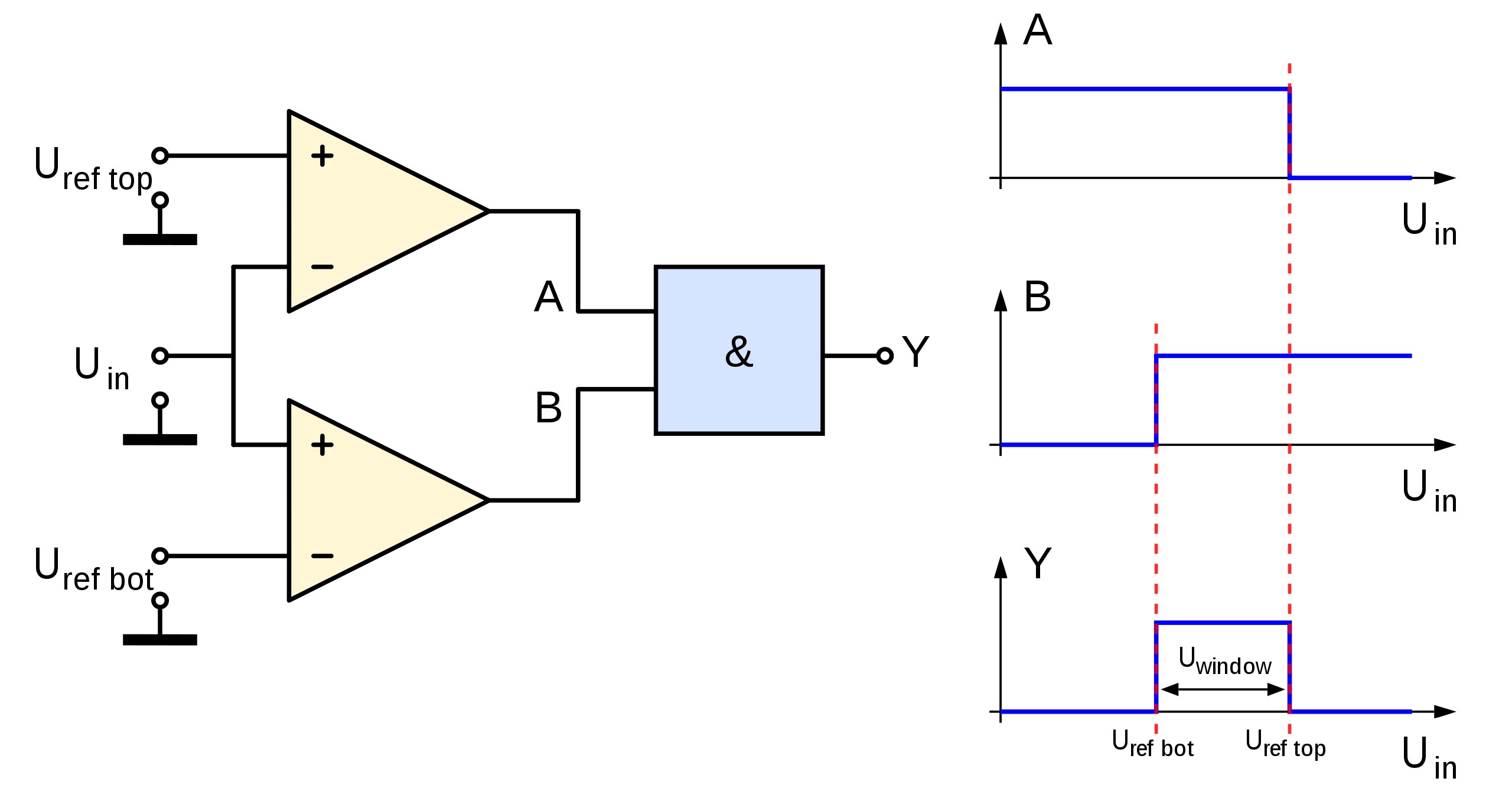
Window comparators, also called window detector circuits or dual edge limit detectors, are used to determine if an input is between two precise reference voltages. A window comparator can be built with two comparators in parallel to determine if a signal, Uin, is between two reference voltages, Uref top, and Uref bot. If the signal is in the window between the references, the output is high; if not, the output is low. Each comparator compares the input signal against one of the references. The outputs are sent through a logic gate, such as an AND gate which outputs the digital signal (Figure 3). Applications for window detectors range from level sensors, battery voltage monitors, and testing systems to various industrial process alarm devices.
Op amp as a comparator
In a limited number of applications requiring low offset voltage, VOS, low input bias current, IB, wide common mode rejection, CMR, and low-speed operation, op amps can be used as comparators. Using op amps as comparators is not generally recommended if speed, stability, and hysteresis are important.
Figure 4 shows op amps as comparators with and without feedback. The circuit on the left amplifies the voltage difference between the input and reference voltages. If Vin is greater than VREF, the output voltage will rise to the positive saturation voltage; if Vin is lower than VREF, the output voltage falls to its negative saturation level. This basic circuit has no negative feedback. It has a very high open-loop gain; small amounts of positive can start oscillating during transitions. Positive feedback can be difficult to eliminate. It can be caused by output currents flowing into a common ground impedance, by stray capacitances between the noninverting input and the output, and so on. Performance can be improved by adding a hysteresis voltage to the basic circuit, reducing its sensitivity to noise.

Summary
Op amps and comparators are similar but not the same. For example, the output of comparators is a logic signal designed to operate in an open loop configuration. Comparators that operate with inputs of frequencies, binary numbers, currents, and voltages are available. Op amps can have only voltage or current inputs and their outputs and are designed for closed-loop applications with feedback from the output to the inverting input. In a limited number of applications, op amps can be used as comparators, but comparators are never suitable substitutes for op amps.
References
Op Amp as Comparator, Analog Devices
Op Amp Types, Rohm
Op-Amps, Comparator Circuit, Renesas
Opamp vs Comparator, Gadgetronicx
Operational transconductance amplifier, Wikipedia
What is an Operational Amplifier?, Monolithic Power Systems
Window detector, Wikipedia