A precision rectifier, sometimes called a super diode, is an op amp circuit designed to behave like an ideal diode and is used in high-precision signal processing applications. It’s not a synchronous rectifier. The op-amp-based precision rectifier should not be confused with power MOSFET-based synchronous rectification. Because there is no diode voltage drop between the input and output, a precision rectifier can rectify very small voltages, much smaller than the typical diode forward voltage of 0.7V, or even the on-resistance of a synchronous rectification MOSFET. This FAQ reviews the benefits, configurations, and applications of precision rectifiers.
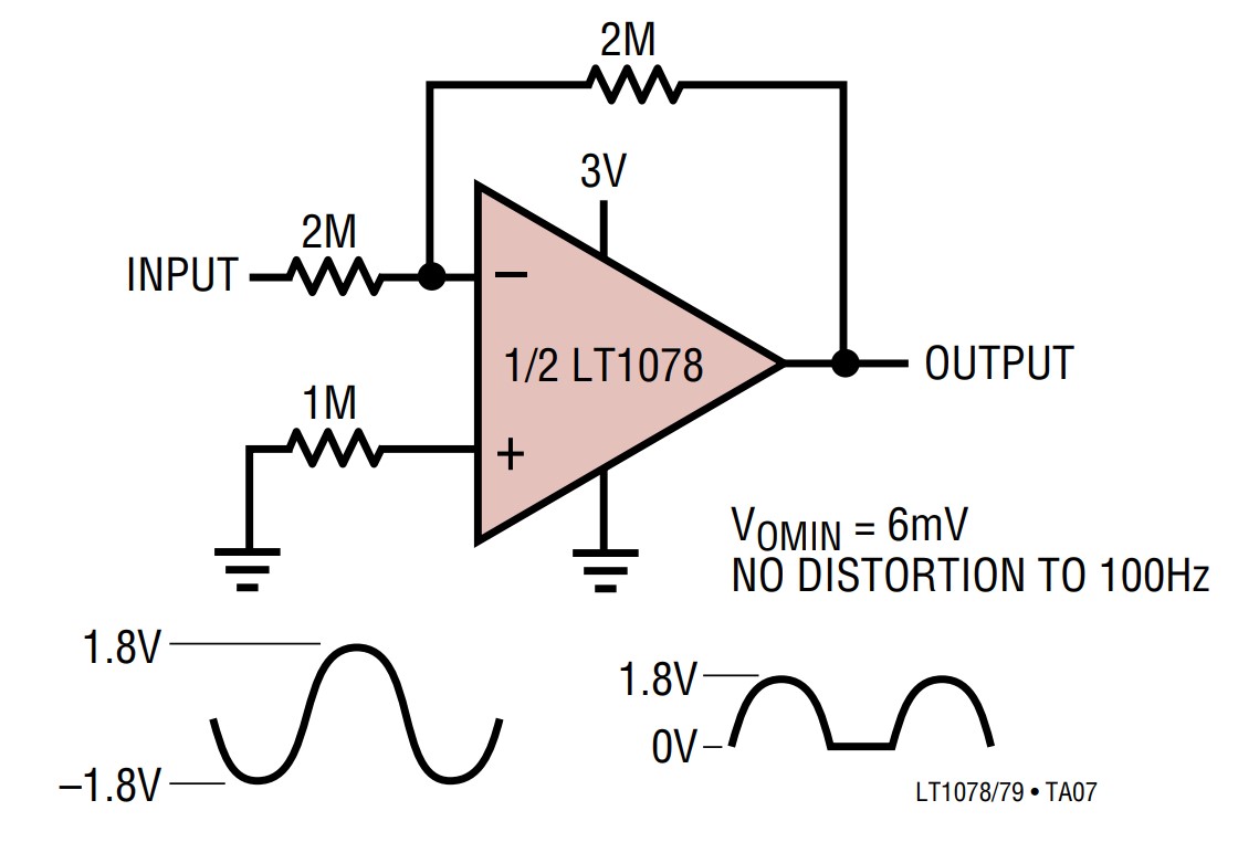
Precision rectifiers find use in audio, instrumentation, current sensing, biomedical sensors, and other applications. The simplest precision rectifier is a half-wave topology (Figure 1). Simple precision rectifiers do not work well with high-frequency signals. The half-wave rectifier shown below and the full-wave rectifier presented next are generally limited to 100Hz or less. Other simple precision rectifier designs are available that can operate up to 1kHz.
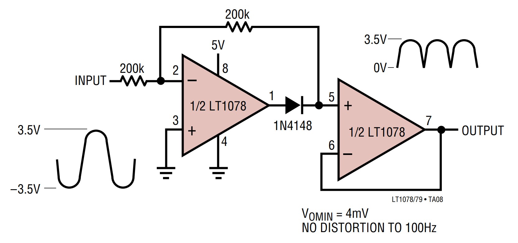
A precision full-wave rectifier (also called an absolute value circuit) consists of a precision half-wave rectifier, followed by an inverting summing amplifier (Figure 2). The input voltage is applied to the input of the precision half-wave rectifier section and through a resistor to the input of the summing amplifier section. The precision half-wave rectifier section uses an inverting amplifier configuration, and the output of the full-wave precision rectifier is the absolute value of the input waveform.
Precision rectifier for current sensing
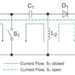
In some applications, it’s useful to produce a DC signal from an AC current transformer (CT) for use by a programmable logic controller (PLC), motor controller, or data acquisition system. Rectifying the AC output of the CT to produce an accurate measurement using a conventional rectifier diode can pose challenges due to the diode voltage drop and variances over current and temperature. A precision rectifier can overcome those limitations (Figure 3). In this circuit, the CT output is applied across resistor R1, and the AC voltage is rectified by the first op amp and amplified by the second op amp.

In this application, the gain of the first op amp stage is kept at unity with R2 = R3 to preserve the symmetry of the rectified waveform. To maintain good accuracy, R2 should be at least 10x the value of R1. To boost the rectified voltage to the needed level, the gain of the second stage is determined by (R5/R4) + 1.
A precision rectifier can be used to measure an AC input voltage as low as 10 mV in some applications, which is then amplified to a useful level. That enables the use of smaller cores and inexpensive core materials, reducing cost, all while improving accuracy. The output RC filter should be designed with a time constant at least 10x greater than the frequency of the CT output.
Higher frequency operation
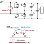
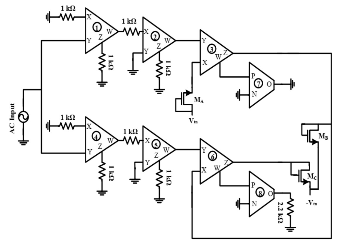
A full-wave precision rectifier can be configured to operate up to 1MHz or higher with some additional circuitry. For example, adding two dual-output current conveyors (a type of unity gain amplifier) and five MOSFETs can boost the frequency range of a full-wave precision rectifier and provide low ripple and total harmonic distortion on the output (Figure 4). The circuit produces a dc output voltage with an amplitude that closely matches the peak input voltage over a range of 50 Hz to 1 MHz with high precision, wide bandwidth, and high accuracy.

Tunable precision rectifiers
Tunable precision rectifiers can be designed that include an external bias voltage to control the rectified output of the circuit while providing high input impedance, low output impedance, and better slew rate. A high input impedance minimizes the load on the input source, while a low output impedance supports the maximum output voltage. One proposed tunable full wave precision rectifier design with those specifications uses a voltage mode scheme combined with analog building block differential voltage current conveyor transconductance amplifiers (DVCCTA) (Figure 5). This design is especially suited for low voltage and high-frequency input signals. The output waveform is made tunable by controlling the bias voltage.
Summary
Precision rectifiers are versatile circuits. They rectify AC signals as low as 10 mV with no diode voltage drop between the input and output and find applications in various audio, instrumentation, and sensing designs. While basic precision rectifier implementations are limited to low-frequency operation, more sophisticated designs can operate to 1MHz or higher frequencies, and tunable precision rectifiers can be designed that combine high input impedance, low output impedance, and improved slew rates.
References
A New Precision Peak Detector/Full-Wave Rectifier, Journal of Signal and Information Processing
Build a Full-Wave Rectifier Circuit with a Single-Supply Op Amp, Analog Devices
Electronically Tunable Full Wave Precision Rectifier Using DVCCTAs, MDPI electronics
Precision Full-Wave Rectifier, Dual-Supply, Texas Instruments
Precision Rectifier, Wikipedia
Precision Rectifier Circuit for CT Signal Conditioning, CR Magnetics