An amplifier design from 1936 gets a revival by reducing power consumption in cellular radios.
The quest for better energy efficiency in 5G includes the base station power amplifier (PA). The large number of small cells coming online [Ref. 1] amplifies the need for efficiency, with some claiming that 5G will stress the power grid. Having covered RF power efficiency, and envelope tracking, we now look at the Doherty Amplifier as a technique for reducing energy consumption.
William H. Doherty invented this amplifier in 1936, for use in high-power AM broadcast transmitters [Ref. 2]. The technique dramatically improved the amplifier efficiency from about 30% to over 60%. The key gain device at the time was the vacuum tube, but the same approach is now applied to many different semiconductor technologies (CMOS, GaAs, LDMOSFET, and GaN).
Varying power level
Wireless communications signals often have high peak-to-average power ratio (PAPR), as shown in Figure 1. (Note that this is a plot of power vs time, not voltage.) If an amplifier is designed to operate efficiently at the peaks (and with good linearity), it will be much less efficient at average power levels. As shown in the figure, we can consider the signal operating in two regions, low power and high power.
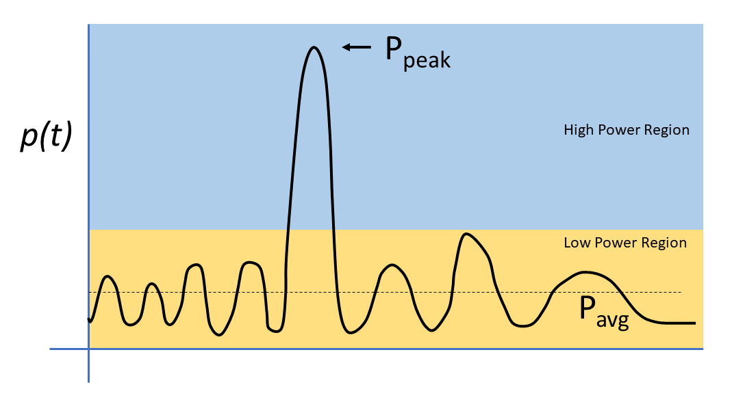
Figure 1. Wireless signals often have a high Peak-to-Average Power Ratio (PAPR).
The Doherty amplifier uses two amplifiers to optimize the overall PA performance. The carrier amplifier (or main amplifier) handles the low-power region while the peaking amplifier (or auxiliary amplifier) handles the high-power region. This sounds simple, but the practical implementation can be challenging.
Figure 2 shows a classic Doherty amplifier with two amplifier paths, both fed from a hybrid coupler. The carrier amplifier is always on while the peaking amp remains idle unless the signal moves into the high-power region. In the high-power region, the peaking amp turns on and provides additional amplification to support the higher output power. Two important design challenges are 1) splitting and recombining the signal while maintaining time alignment 2) turning on the peaking amplifier under the proper conditions while maintaining linearity.
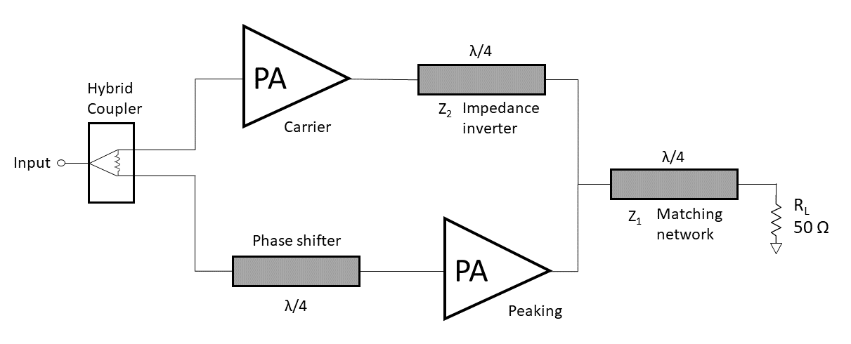
The classic Doherty amplifier uses two amplifier paths to optimize power efficiency.
Many modulation techniques depend on maintaining amplitude and phase purity, so it is important that the combined operation of the carrier and peaking amplifiers is linear. Various papers refer to the carrier amplifier as operating in Class A, Class B or Class AB, with the main point being that the amplifier needs to operate linearly. The peaking amplifier is often described as operating in Class C, which means that the amplifier is only biased on part of the time. Class C is normally associated with non-linear operation and may not be suitable for amplifying all types of modulation. The Doherty amplifier, however, incorporates the peaking amplifier as an add-on device such that linearity is maintained at the output.
The classic Doherty design uses a quarter-wave (λ/4) transmission line to provide an impedance inversion at the output of the carrier amplifier. This quarter-wave line introduces a 90-degree phase shift, so an additional quarter-wave line is added ahead of the peaking amplifier to align the two paths. There is usually an additional quarter-wave line at the output of the Doherty amplifier, to provide an impedance match to 50 Ω. Some designs use lumped circuit elements in place of the transmission lines. See Ref. 3 for a more detailed look at the circuit design.
The power efficiency of the Doherty amplifier has an inflection point where the peaking amplifier is engaged (Figure 3). The power efficiency may drop somewhat above the inflection point but the amplifier still maintains efficiency. As shown in the figure, the peaking amplifier typically turns on at 6 dB below the peak output power.
While the classic Doherty design uses only two amplifier paths, some designs use additional peaking amplifiers to improve the performance in the high-power region.
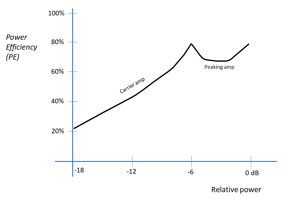
Figure 3. The Doherty amplifier power efficiency curve often has an inflection point where the peaking amplifier is activated.
DSP Improvements
Variations on the Doherty amplifier have emerged over time as engineers invent ways to improve its performance and adapt it to specific applications. An internet search will quickly reveal a huge number of articles discussing these Doherty configurations.
One such improved block diagram uses digital signal processing (DSP) for the baseband system driving the amplifier (Figure 4). Quadrature (I/Q) data streams are converted to analog form and upconverted to the desired radio frequency band. The DSP block also provides a control signal for the peaking amplifier. This signal can adjust the power-supply voltage (or other bias control) of the peaking amp, based on the instantaneous power in the signal. This approach essentially adds envelope tracking to the Doherty amplifier for better performance.
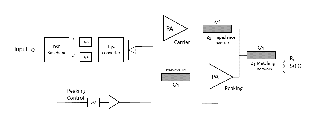
Figure 4. A DSP baseband system can improve the performance of a Doherty amplifier.
The DSP baseband block can also improve the distortion in the signal by applying digital predistortion (DPD), a common technique that corrects for the distortion found downstream in the amplifier paths by applying an inverse function to the upstream signal. We “predistort” the signal so that it is less distorted after it passes through the amplifier and emerges at the output.
The amplifier shown in Fig. 4 is an example of a modern RF amplifier designed with a specific type of signal in mind. This amplifier is not a generic linear time-invariant amplifier that works well with all types of signals. Instead, it is optimized for a particular wireless format (e.g., LTE, 5G, WiFi 6).
The Doherty amplifier is a rich topic with an interesting history. In this article, we have introduced the basic concepts of how the amplifier works. To explore the topic further, see References 3 to 6.
References
- SCF Market Status Report July 2020. Small Cell Forum, https://scf.io/en/documents/050_-_Small_cells_market_status_report_July_2020.php
- W.H. Doherty, “A New High Efficiency Power Amplifier for Modulated Waves,” Proceedings of the IRE, September 1936. https://ieeexplore.ieee.org/document/6773288
- R. Pengelly, C. Fager and M. Ozen, “Doherty’s Legacy: A History of the Doherty Power Amplifier from 1936 to the Present Day,” IEEE Microwave Magazine, Feb. 2016. https://ieeexplore.ieee.org/document/7379107
- A. Grebennikov and S. Bulja, “High-Efficiency Doherty Power Amplifiers: Historical Aspect and Modern Trends,” Proceedings of the IEEE, Dec. 2012. https://ieeexplore.ieee.org/document/6302162
- C. Fager, W. Hallberg, M. Özen, K. Andersson, K. Buisman and D. Gustafsson, “Design of linear and efficient power amplifiers by generalization of the Doherty theory,” 2017 IEEE Topical Conference on RF/Microwave Power Amplifiers for Radio and Wireless Applications (PAWR), Phoenix, AZ, 2017. https://ieeexplore.ieee.org/document/7875565
- James E. O’Neal, “Reinventing Bill Doherty and His High-Efficiency Amplifier,” RadioWorld, April 25, 2016. https://www.radioworld.com/columns-and-views/reinventing-bill-doherty-and-his-highefficiency-amplifier
Related articles:
- How to calculate RF power amplifier efficiency
- Envelope tracking improves power amplifier efficiency
- What are amplifier classes and their power efficiencies?
- 5G needs better amplifier efficiency