by Matthew Ballance, Mentor, a Siemens Business
Register tests are a very useful smoke test at all design levels — from IP to subsystem to SoC. While the built-in register-test sequences in the UVM library are useful at the IP level, capturing register-test intent in a PSS model makes register-test functionality portable from the IP to the SoC level and provides more flexibility in controlling which registers are checked in a given test run.
In the first article of this four-part EEWorld series, we showed you how to capture register models for subsystem or SoC level tests. In this article, we show you how to produce register-access tests and run them.
Generating register-access test intent
First, we need to create a PSS model of the register-access test intent, which must be constrained, based on the registers in the design tested. Fortunately, we already captured all the information needed to generate these constraints in our register model (see Part 1).
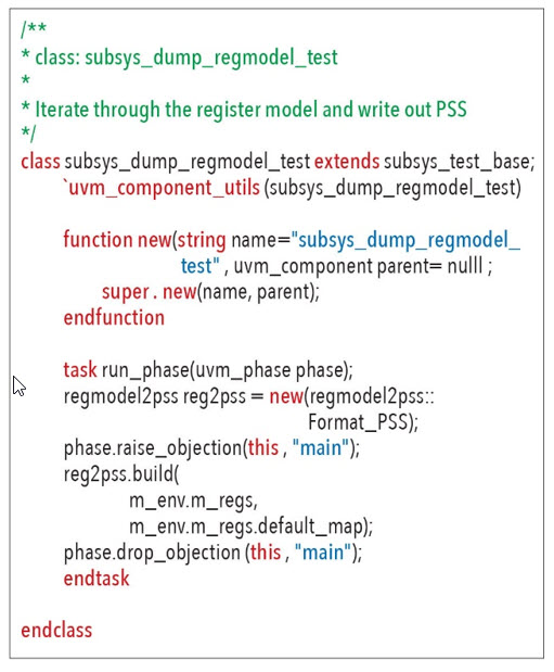
Our register-creation tool may be able to construct PSS register tests directly as one of its outputs. If not, then one approach to automating test intent creation is to run some SystemVerilog code that iterates through the UVM register model and writes out the PSS register-test intent. The code below shows a UVM test that calls a class named regmodel2pss to create PSS test intent from the UVM register model.
The result is a portable stimulus description that captures the register-test intent for the subsystem register map. The code below is the first portion of the PSS component and PSS action generated to test the register model.
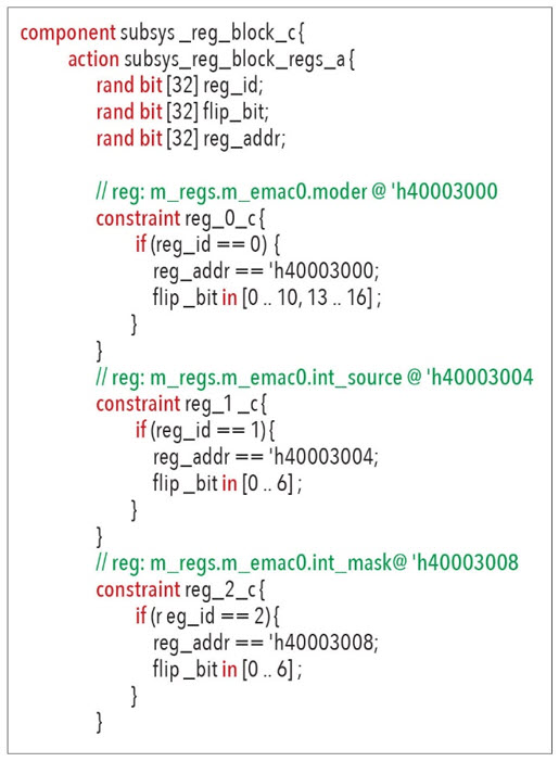
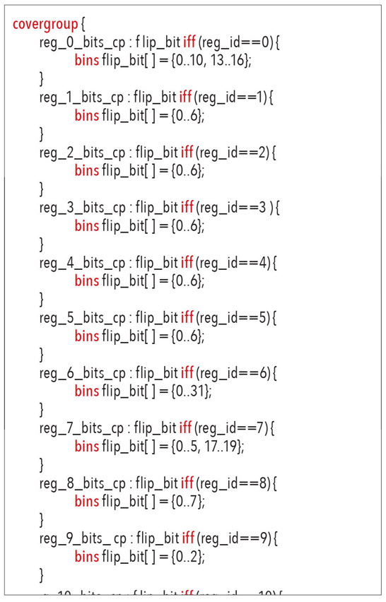
The action (named from the register-block name) declares three rand fields. The reg_id field contains an ID for the targeted register and ranges between 0 and the number of registers minus 1. The flip_bit field specifies the register bit to be tested. flip_bit and reg_addr are auto-constrained based on the register id to ensure the action produces a valid register address and flip_bit based on the tested register. A PSS coverage model can also be automatically generated to ensure that all registers and all bits within the registers are covered, as shown below.
The test scenario shown below is built on top of the core action that encodes the test intent. Once we have the core register-test intent, we need to integrate it into a top-level PSS scenario. While our core register-test intent was automatically derived from the register model, our top-level register test scenario will be written by hand.
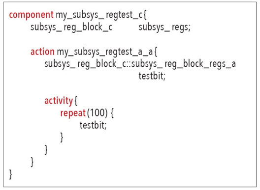
The test scenario is encapsulated in a top-level component, as required by PSS. Because we will use the action from this component, we generate an instance of the register-test component (subsys_reg_block_c) inside the top-level component. In our top-level action (my_subsys_regtest_a), we create an instance of the subsys_reg_block_regs_a action named testbit. Inside this action is an instance of the register-test fields and covergroup. In the top-level action’s activity, we run testbit 100 times, which means that we will test 100 register bits each time our test runs.
Adding the test realization layer
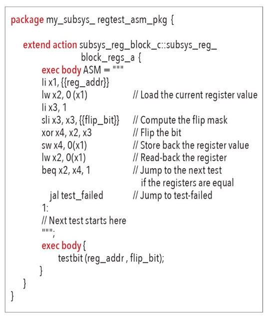
Now we need to connect this test intent to specific verification environments with test realization, as our top-level test scenario doesn’t actually do anything until it includes test realization. Fortunately, PSS allows us to easily layer in test realization without changing the core description — in this case, the subsys_reg_block_regs_a action. The code below is a test realization description for SystemVerilog that leverages the PSS procedural interface. The signature of an external function is declared and that function is invoked from the exec block of an action

In the test realization snippet above, we use a PSS target-template exec block to specify a snippet of assembly code (RISC-V in this case) that must be generated to test a register bit. The curly braces (e.g., {{reg_addr}}) are used to reference the current value of a field in the PSS model and substitute that value into the generated code. Doing test realization in assembly language certainly has its limitations, but PSS makes it possible when that’s the technique that is needed. This style of test realization works for any environment that supports callable procedures; e.g., C, C++, SystemVerilog, etc. In most cases, our bare-metal embedded software tests for our SoC will be written in C. But, what if we needed to produce an assembly-language test? Fortunately, PSS provides a way to do this as well!
Running the PSS tests
Now that we have test intent and test realization to test access to our registers, we can begin running tests. In a UVM environment, PSS gives us the flexibility to either pre-generate directed tests or run a PSS solver engine while running simulations.
The directed UVM test shown below is very easy to understand, and it always does exactly the same thing.
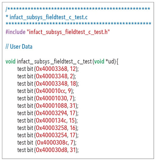
If we are able to use C in our bare-metal software environment, we can use the testbit function implementation and the PSS procedural interface to generate the C test code, as shown below. But what if we want our tests to do something slightly different whenever we run different seeds? This is where running a PSS solver engine with simulation is advantageous. Running the same sequence with different seeds results in different behavior, and PSS tools provide dedicated features for dynamically partitioning tests across simulations running in regression.
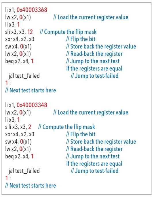
However, if we need to use assembly code, we can use our target-template exec block test realization to generate a fully standalone test. A snippet from that test is shown below with tests for two register/bit combinations.
Conclusion
Both the input files to register-generation tools and the resulting UVM register model contain sufficient information to automatically create portable stimulus test intent. This makes it very easy for register-generation tools to add support for portable stimulus tests. It also makes it very easy to derive portable stimulus tests from existing UVM register models, regardless of how they were constructed. Either way, the result is more verification automation with PSS!
Additional Resources:
Making Legacy Portable with the Portable Stimulus Specification
Automating Tests with Portable Stimulus from IP to SoC Level
 Matthew Ballance is a Product Engineer and Portable Stimulus Technologist at Mentor Graphics, working with the Questa inFact Portable Stimulus product. Over the past 20 years in the EDA industry, he has worked in product development, marketing, and management roles in the areas of HW/SW co-verification, transaction-level modeling, and IP encapsulation and reuse. Matthew is a graduate of Oregon State University.


Leave a Reply
You must be logged in to post a comment.