High-voltage dc power transmission (HVDC) use is growing across a variety of applications. One of the main growth drivers is renewable energy. HVDC interconnects between geographically dispersed wind and/or solar farms can help mitigate the effects of variable energy generation levels by providing a means for averaging the various changing power outputs. HVDC is already used to bring hydropower from remote generation sites to urban centers.
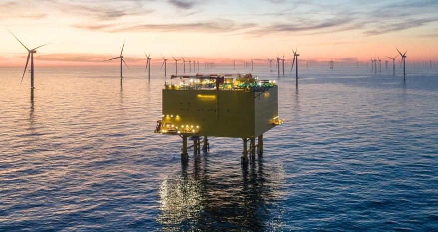
AC transmission lines can only interconnect synchronized AC networks. HVDC is often used to connect unsynchronized AC power networks. For example, Japan has 50Hz and 60Hz networks; there are multiple unsynchronized AC networks in North America, South America, and the Middle East. In addition, offshore wind farms use HVDC to combine the outputs from numerous unsynchronized wind turbine generators for transmission to shore on an underwater cable. And in the case of underwater interconnects, HVDC is less costly than HVAC for distances as short as 50km.
Since HVDC is based on electronic power converters, it can manage multiple power grids by controlling the amounts and directions of power flow. As a result, it can improve grid stability and provide alternative energy sources during high demand times. That is already helpful in California. The use of the Western Interconnection system enables the state to use a higher percentage of renewable energy than would be possible if the state were an “electricity island.” With the variety of HVDC power transmission applications, it’s not surprising that there are multiple HVDC system architectures.
HVDC system architectures
There are several common architectures for HVDC systems, including monopolar, bipolar, back-to-back, and multi-terminal. In a monopolar HVDC link, a single conductor is used, and the other side of the rectifier is connected to the ground. Monopolar links using overhead cables are usually limited to 1.5GW, while monopolar links using underground or underwater cables are limited to about 600MW. Monopolar HVDC transmission systems are the least used architecture. When used, most monopolar systems are designed for future capacity expansion into a bipolar system.
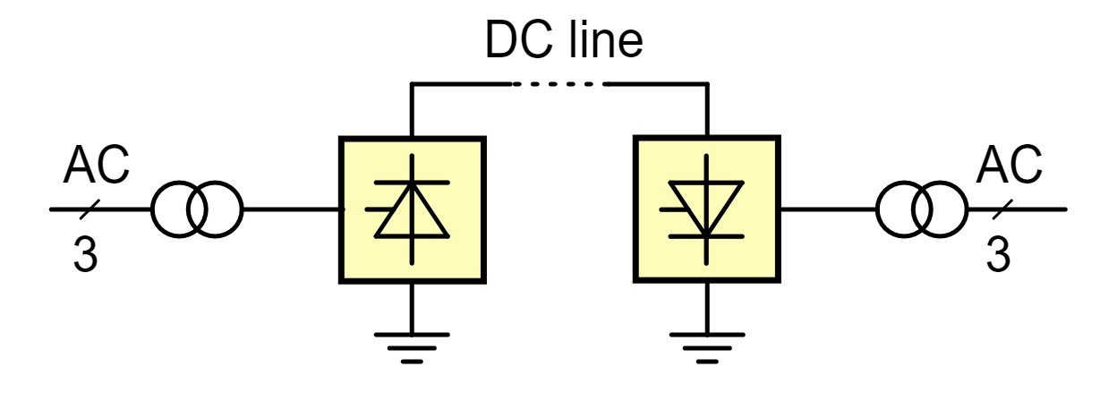
A variation on the monopole architecture is the symmetrical monopole, which uses two high-voltage conductors, each operating at half of the transmission voltage. The symmetrical monopole transmission architecture is rarely used with line-commutated converters but is commonly seen with voltage-sourced converters. (for an overview of line-commutated versus voltage-sourced HVDC converters, see part two of this FAQ series, “HVDC converters, components, and control systems”).
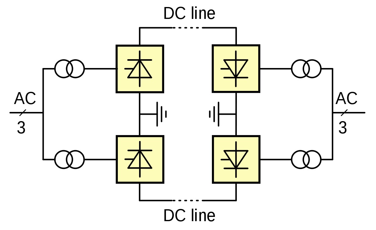
Bipolar HVDC transmission uses a pair of cables, both with high potential with respect to ground, in opposite polarity. Bipolar systems can carry up to about 4GW at ±660kV with a single converter per pole. Since each cable needs to be insulated to the full voltage difference, cabling costs for a bipolar system are higher than a monopolar design. Bipolar systems have inherent flexibility. For example, if a fault develops in one line, about half the rated power will continue to flow by switching to monopolar mode. In addition, the two cables can be carried on different sets of transmission towers, providing additional resilience.
Back-to-back HVDC systems are not used for power transmission over any distance. They typically consist of two converters in the same building and are used to connect incompatible AC grids such as:
- In Japan, South America, and the Middle East, back-to-back HVDC systems are used to join 50Hz AC grids with 60Hz AC grids.
- Back-to-back HVDC systems are used in Europe to join two AC networks of the same frequency, but no fixed phase relationship.
- Around the world, back-to-back HVDC systems are used to connect power systems with different operating frequencies and different phase numbers, such as connections between AC utility services and traction power stations for railroad systems.
Finally, there are multi-terminal HVDC systems. Multi-terminal systems can be configured in parallel, series of a mixture of parallel and series. Larger systems tend to uses parallel architectures. Before the development of voltage-sourced converters (VSCs), multi-terminal HVDC systems were difficult to design. In a system based on line-commutated converters, reversals of power are implemented by reversing the DC voltage, which affects all converters connected to the system. With VSCs, power reversal is achieved by reversing the direction of current flow, making parallel-connected multi-terminal systems easier to manage. As a result of the development of VSCs, multi-terminal systems are becoming increasingly common.
UHVDC
Ultra-high voltage DC (UHVDC) power transmission can increase the efficiency of electricity transmission over longer distances. A typical loss for 800 kV lines is 2.6% over 800 km. Increasing the transmission voltage reduces the power loss, but the interconnection components required (especially the transformers) were prohibitively expensive until recently.
Developments in transformer design and production have enabled UHVDC. The biggest challenge in developing UHVDC transformers was the insulation system. There are now 1,100kV UHVDC converter transformers. As a result of advanced transformer manufacturing methods, it’s now possible to transmit power at voltages of 1000kV, ±800kV, and even ±1100kV.
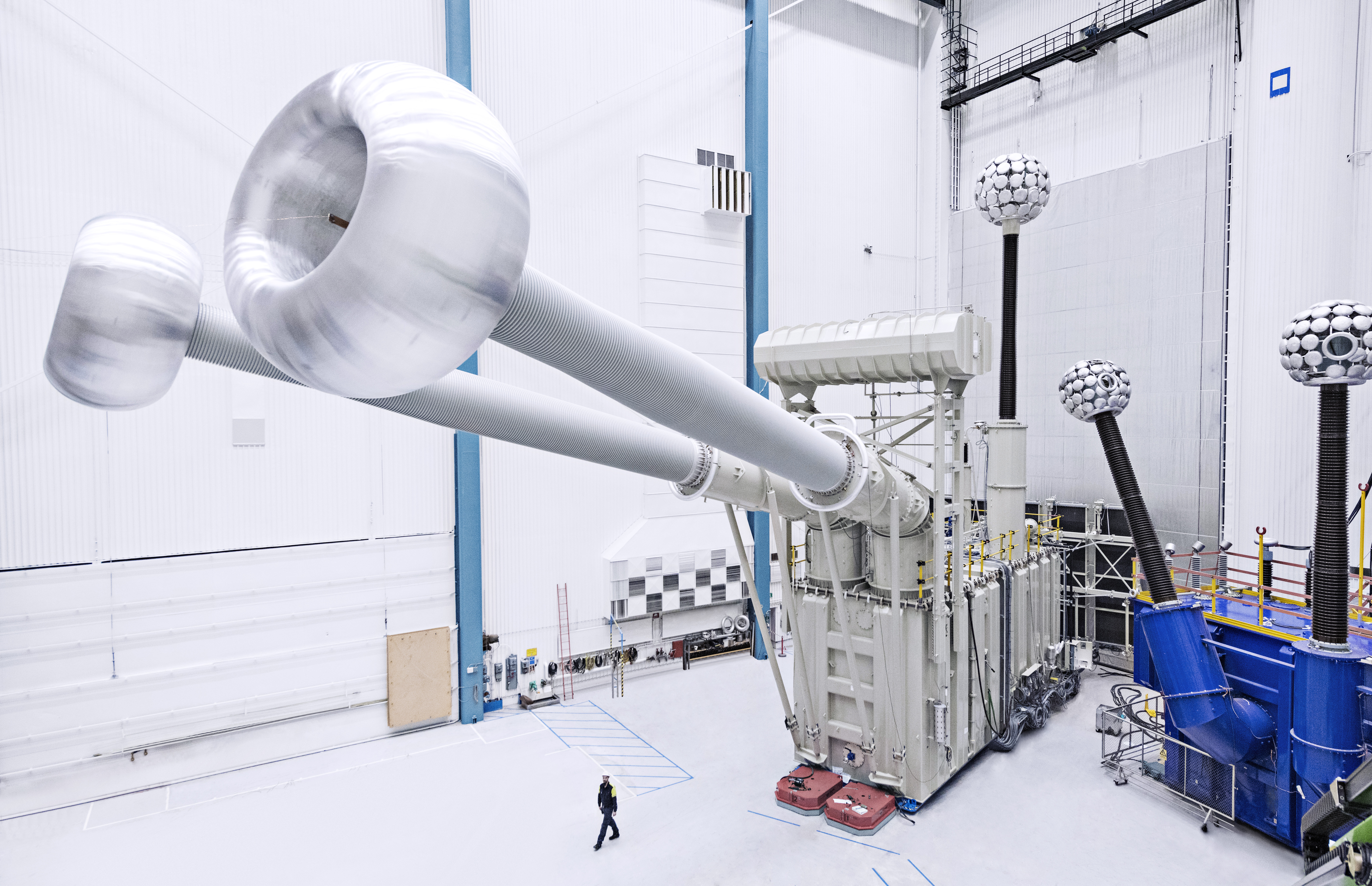
Both valve bushings through which the current flows from a 1,100kV transformer into the valves are approximately 19 meters long. Overall, the transformer is 37.5 meters long, 14.4 meters high, and 12 meters wide. In operation, the transformer weighs 909 metric tons. The efficiency of the converter transformer is well above 99%. It’s rated for nearly 600MVA. As noted in part two of this FAQ series, it’s necessary to control the transformer’s size for logistical reasons. It is impractical to transport transformers that are too large.
HVDC light and HVDC plus
HVDC Light, from Hitachi ABB Power Grids, based on VSC technology, is designed to transmit power underground and underwater, also over long distances. HVDC Light increases the reliability of power grids, and the technology extends the economic power range of HVDC transmission down to just a few tens of megawatts. In the upper range, the technology now reaches 3,000 MW and ±640kV – enough electricity to power several million households and enabling power transmission over 2,000 kilometers.
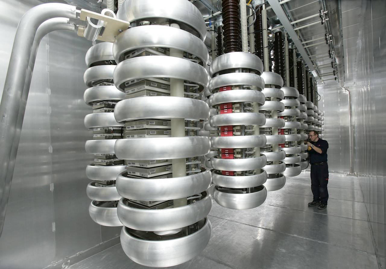
The system design enables compact converter stations – a big benefit in applications like offshore wind and interconnections. It offers numerous environmental benefits, including “invisible” power lines, neutral electromagnetic fields, oil-free cables, and compact converter stations. It is quick to install and provides an alternative to conventional AC transmission systems and local generation in several cases, such as:
- Connecting wind farms to power grids
- Underground power links
- Providing shore power supplies to islands and offshore oil & gas platforms
- Connecting asynchronous grids
- City center infeed
Utilities are under pressure to meet consumer and regulatory demands for high quality, competitively priced power supply that has a low environmental impact. The expansion of AC transmission capacity is often limited by local planning regulations and residents’ concerns who object to installing new overhead lines. It is now economically feasible to expand transmission capacity using underground HVDC cables. This approach not only minimizes environmental impacts but it also improves the quality of the power supply.
Targeting similar applications, Siemens Energy offers HVDC PLUS systems to provide solutions for challenges such as the reliable power supply of metropolitan areas, the improvement of grid stability, and grid access for offshore wind farms. HVDC PLUS is suitable for back-to-back operation and long-distance cable and overhead line HVDC transmission, and it can be integrated into multi-terminal HVDC systems and future HVDC grids.
Siemens Energy uses modular multilevel VSC converters in a six-pulse bridge topology. One converter comprises three identical phase units with two valves, and each valve contains a number of power modules supporting the full DC voltage. Each power module contributes only a small voltage step and is controlled individually. Practically speaking, each module within an MMC is a discrete voltage source with a local capacitor to define its voltage step without creating ripple voltage distortion across the converter’s other phases. That way, it is possible to achieve the required sinusoidal AC and smooth DC side output voltage waveforms without excessive harmonic distortion and high-frequency noise.
The IGBTs at the heart of the power modules are fully controllable. This enables modular multilevel converters to absorb and generate reactive power independently from active power up to the converter rating. The output currents can be varied over the complete operating range in a smooth, linear way. This enables independent and flexible control of active and reactive power, supporting the connected AC grid.
That concludes this three-part FAQ series on high-voltage dc power transmission. You might also enjoy reading part 1, “Over a Century of High Voltage DC Power Transmission” and part 2, “HVDC converters, components, and control systems.”
References
ABB achieves breakthrough with world’s most powerful HVDC transformer, ABB
Green Power Superhighways Building a Path to America’s Clean Energy Future, a joint publication from American Wind Energy Association and the Solar Energy Industries Association
High-voltage direct current, Wikipedia
HVDC Light (VSC), Hitachi ABB Power Grids
HVDC PLUS, Siemens Energy

