• Skip to primary navigation
  • Skip to main content
  • Skip to primary sidebar
  • Skip to footer

Electrical Engineering News and Products

Electronics Engineering Resources, Articles, Forums, Tear Down Videos and Technical Electronics How-To's

  • Products / Components
    • Analog ICs
    • Connectors
    • Microcontrollers
    • Power Electronics
    • Sensors
    • Test and Measurement
    • Wire / Cable
  • Applications
    • Automotive/Transportation
    • Industrial
    • IoT
    • Medical
    • Telecommunications
    • Wearables
    • Wireless
  • Resources
    • DesignFast
    • Digital Issues
    • Engineering Week
    • Oscilloscope Product Finder
    • Podcasts
    • Webinars / Digital Events
    • White Papers
    • Women in Engineering
  • Videos
    • Teschler’s Teardown Videos
    • EE Videos and Interviews
  • Learning Center
    • EE Classrooms
    • Design Guides
      • WiFi & the IOT Design Guide
      • Microcontrollers Design Guide
      • State of the Art Inductors Design Guide
    • FAQs
    • Ebooks / Tech Tips
  • EE Forums
    • EDABoard.com
    • Electro-Tech-Online.com
  • 5G

Including the often overlooked 1/f current noise

August 2, 2021 By Bonnie Baker

It is tempting to center your attention only on voltage noise when using operational amplifiers in the circuit. This impulse is attractive because the current noise is always well below the voltage noise specifications. But be careful. Don’t jump to conclusions without looking at all the elements in this noise challenge. This blog explores the amplifier current noise issues and how it can compete with the well-known voltage noise contribution.

What type of op amp are you using?

To be confident of your noise calculations, take note of your circuit configuration and op amp type. Op amp circuits most often have resistors at the amplifier input and feedback loop. The resistor elements create flat white noise; however, there is another dynamic to consider. Your amplifier can generate sizable current noise that resistors will further gain to the noise signal. Consider the circuit in Figure 1.

Figure 1. This amplifier buffer has a large input impedance that produces its own noise and interacts with the input current noise.

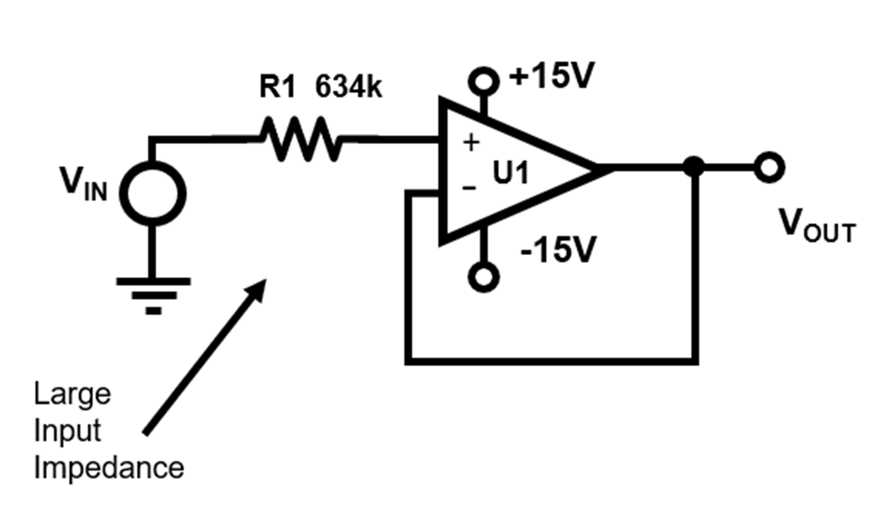
This simple circuit has a large input impedance into the non-inverting input. If the amplifier has considerable 1/f current noise, a significant noise error appears at the input terminal. If you have a high precision low noise system, the proper amplifier selection for this circuit is critical.

Common amplifier choices are between the bipolar and CMOS (Figure 2).

Figure 2. Amplifier Input stage Bipolar and FET transistors

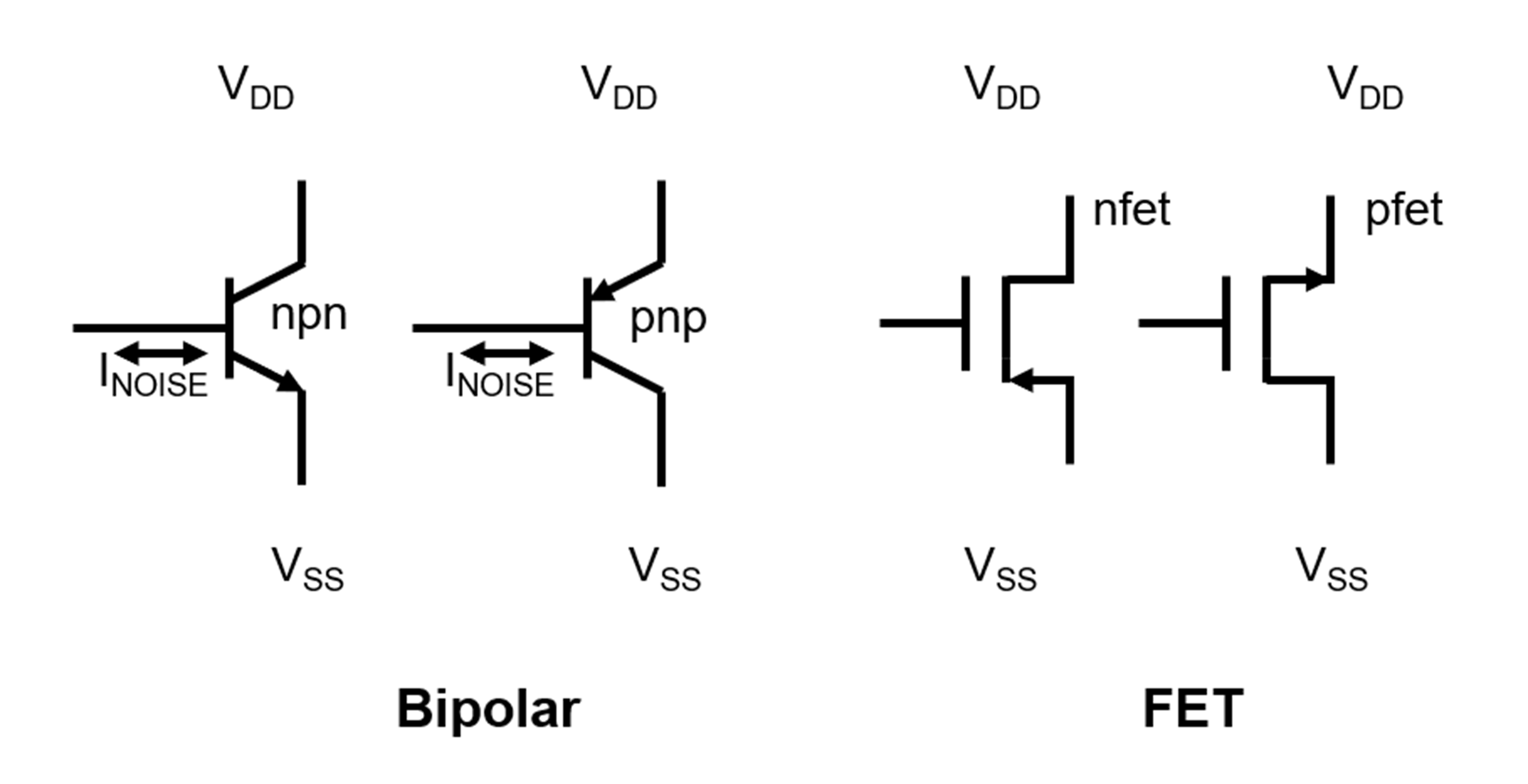
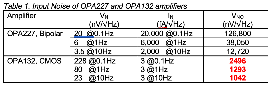
The bipolar amplifier input devices tie directly to n-material or p-material. In both cases, these input devices have higher input bias current and input current noise. The CMOS (Complementary Metal Oxide Semiconductor) amplifier input devices tie directly to the transistor’s gate. The amplifier devices have extremely low input current noise in both CMOS cases, as illustrated in Table 1.

Which amplifier gives the lowest output noise?

The low noise, bipolar amplifier, TI’s OPA227, low voltage noise is instinctively the best choice. But take a second look. The device’s current noise is higher than TI’s OPA132. Carefully compare the low-frequency noise of the two amplifiers. Since this application circuit has high input impedance, the current noise looks incredibly significant. The FET input OPA132 has the highest voltage noise, but the OPA132 low current noise wins the contest for this application circuit.

Surprisingly, the OPA227 has the worst noise, but this is due to the high amplifier current noise that the large input impedance converts to voltage noise. But take a second look. Low impedance applications would likely make the OPA227 the best choice.

The VNO formula applied to the number in Table 1 is:

Where k = 1.38e-23 (Boltzmann’s Constant)
T = temperature and Kelvin

The resistor noise formula is:

Equation 2.

To answer the question above is surprising. The amplifier that produces the lowest output noise combines a low-value input resistance and bipolar amplifier.

Conclusion Current noise is a surprise when calculating 1/f noise because we habitually concentrate on the voltage noise and leave it at that. This blog tackles the current noise issue and compares it by working with Bipolar and FET amplifiers.

Finally, the 1/f noise mystery is solved. We saw how to calculate voltage noise in this region and then pull current noise into the discussion. But wait. There is one more issue to consider. In part 3 of this series, we will change the complete amplifier paradigm from looking at the standard bipolar, FET, and CMOS to the zero-drift amplifiers.


References

Noise Reduction Techniques in Electronic Systems, Henry W. Ott, John Wiley & Sons, ISBN 0-471-85068-3
“Understanding and Eliminating 1/f Noise”, Robert Kiely, Analog Dialogue 51-05, May 2017
“8.8 TI Precision Labs – Op Amps: Noise – 1/F flicker noise”, TI Precision Labs Video, https://training.ti.com/ti-precision-labs-op-amps-noise-1f-flicker-noise

You may also like:


  • Noise quantification and measurement

  • What is passive intermodulation?
  • Negotiate through 1/f noise challenges
    Negotiate through 1/f noise challenges towards sample sizes into the…

  • How to specify a high-frequency PCB

  • Measure power in complex RF signals
DesignFast Banner version: 22e7f758

Filed Under: Analog IC Tips, Analog ICs, FAQ, Featured Tagged With: FAQ

Primary Sidebar

EE Training Center Classrooms

EE Classrooms

Featured Resources

  • EE World Online Learning Center
  • CUI Devices – CUI Insights Blog
  • EE Classroom: Power Delivery
  • EE Classroom: Building Automation
  • EE Classroom: Aerospace & Defense
  • EE Classroom: Grid Infrastructure
Search Millions of Parts from Thousands of Suppliers.

Search Now!
design fast globle

R&D World Podcasts

R&D 100 Episode 7
See More >

Current Digital Issue

April 2022 Special Edition: Internet of Things Handbook

How to turn off a smart meter the hard way Potential cyber attacks have a lot of people worried thanks to the recent conflict in Ukraine. So it might be appropriate to review what happened when cybersecurity fi rm FireEye’s Mandiant team demonstrated how to infiltrate the network of a North American utility. During this…

Digital Edition Back Issues

Sponsored Content

Positioning in 5G NR – A look at the technology and related test aspects

Radar, NFC, UV Sensors, and Weather Kits are Some of the New RAKwireless Products for IoT

5G Connectors: Enabling the global 5G vision

Control EMI with I-PEX ZenShield™ Connectors

Speed-up time-to-tapeout with the Aprisa digital place-and-route system and Solido Characterization Suite

Siemens Analogue IC Design Simulation Flow

More Sponsored Content >>

RSS Current EDABoard.com discussions

  • Help with Verilog replicate operator
  • ESP Serial Communication Problem with RS232
  • How to mark layer comments in CAP of spef file using StarRC
  • MAX5389 resetting by noise
  • Simulation of resonator in HFSS

RSS Current Electro-Tech-Online.com Discussions

  • Will Header and socket hold this PCB OK?
  • Relaxation oscillator with neon or...
  • software PWM
  • MPlab8 remove page breaks in list file
  • ATOM Diy module

Oscilloscopes Product Finder

Footer

EE World Online

EE WORLD ONLINE NETWORK

  • 5G Technology World
  • Analog IC Tips
  • Battery Power Tips
  • Connector Tips
  • DesignFast
  • EDABoard Forums
  • Electro-Tech-Online Forums
  • Engineer's Garage
  • Microcontroller Tips
  • Power Electronic Tips
  • Sensor Tips
  • Test and Measurement Tips
  • Wire & Cable Tips

EE WORLD ONLINE

  • Subscribe to our newsletter
  • Lee's teardown videos
  • Advertise with us
  • Contact us
  • About Us
Follow us on TwitterAdd us on FacebookConnect with us on LinkedIn Follow us on YouTube Add us on Instagram

Copyright © 2022 · WTWH Media LLC and its licensors. All rights reserved.
The material on this site may not be reproduced, distributed, transmitted, cached or otherwise used, except with the prior written permission of WTWH Media.

Privacy Policy