IR cameras can help size up the surface temperatures of electronic components, PCBs, and other objects to reveal unseen problems.
ALAN J. LOWNE, SAELIG CO. INC.
Thermal imagers, also called infrared cameras, capture a 2-D representation of objects in front of their germanium optics (ordinary optical glass impedes IR wavelengths). They present a visible version of thermal energy (heat). These images can be used for immediate diagnosis or processed via software for further evaluation and reporting.

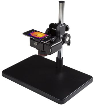
Typical thermal imagers include the Fotric 220 series.
The surface temperatures of electronic components, PCBs, and other objects can be measured with sufficient accuracy to reveal problems unseen to the human eye. A changing or different color representation of the image may indicate overheating in a solder joint, circuit trace, or show a portion of the board that is malfunctioning. It can also accurately measure an IC’s steady state temperature to verify operation within specified limits. In soak-testing imagers can ensure temperature limits are not exceeded on mission-critical boards. Desktop thermal imagers can provide a powerful set of diagnostic tools for testing, debug, and development. A non-contact thermal measurement system which pairs a high-sensitivity infrared camera with an integrated stand lets technicians make quick thermal behavior checks of a PCB or other electronic assembly.
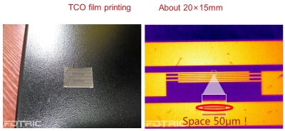
Professional-grade thermal cameras with interchangeable lenses accurately measure temperature and provide high-resolution imaging for a wide range of scientific applications. Some can connect with smartphones, tablets, and computers across Android and Windows systems. Modern thermal cameras are easy to use and can quickly identify problems with PCBs via lenses that can focus down to 20 µm lines. Software provided with some cameras allow picture-in-picture overlays of the heat profile on top of a visible-wavelength image, which helps to visually locate problem areas. Comparing a good board’s thermal image with that of a faulty one can quickly pinpoint where a problem lies, saving valuable debug time.

An example of thermal imaging today, resolving dimensions as small as 20 µm.
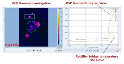
Some cameras can record up to 1,000 frames of full radiometric video, capturing temperature changes in real time with a user-defined sampling rate of up to 5 frames/sec. Up to 640×480-pixel resolution is commonly available and each pixel represents a temperature measurement point in the field-of-view. Data collection can be automatic with no need for an attached PC, allowing an instant analysis of thermal images and videos on the instrument itself.
Individual emissivities can be entered for up to 12 box areas or spots to improve the temperature accuracy of different scenes and materials. Designers can use the radiometric video stream plotting and 3D visualization of temperature images to note hot-spots and subtle temperature changes during product development. Data can be automatically gathered, triggered by time, temperature, or an external signal, with threshold alarms available as well as the capturing of high, low, and average or user-defined temperatures.
Thermal imagers can be valuable for noncontact testing of circuit boards during the design and prototyping phases, but are equally useful in production, soak testing, process monitoring, and quality assurance. Finding and fixing hot spots in electronics designs is somewhat of a guessing game without the assistance of a thermal camera to quickly identify heat dissipation issues and find effective solutions.
Unlike thermocouples or spot pyrometers, IR cameras can take as many as 300,000 individual accurate temperature readings (each pixel!) on large boards or even micro traces. Heat signatures in electronics while charging or in battery use can all be accurately documented in a thermal video during actual charge and discharge. Modern IR cameras can record fast-moving data, with the sensitivity and spatial resolution needed to characterize critical thermal transients.
IN THE DESIGN AND MANUFACTURING PHASE
IR cameras can play a useful role when evaluating circuit design and heat dissipation choices. In some cases, even counterfeit components can be detected because their thermal signature differs from that of authentic parts.
Applying power to the board and letting it run in various conditions and with different loads will insure a reliable finished product. Imaging the thermal signature of powered-up prototype boards can reveal possible electrical or mechanical design improvements. It also helps to avoid unobvious design faults as well as expensive potential product recalls. Discovering that a board or component is overheating can warn a design engineer to investigate active cooling or indicate the need for improved heat-sinking. A circuit design that does not run hot is especially important for prolonging battery life in a final product. The alternative of using thermistors with their associated messy thermal compound on a single point is much less attractive for obtaining accurate and comprehensive temperature measurements.
For quality assurance, a thermal imager viewing powered-up boards can be extremely useful. During automated board inspection, the camera can be controlled by a remote PC to identify, for instance, insufficient solder which raises both circuit resistance and the local temperature enough to be detectable by an IR camera. A faulty circuit will produce a different temperature profile from a good one.

Real-time Thermal Data. Real-time data can be captured to show individual component temperature changes as well as final steady-state conditions.
Model board comparison involves storing a thermal signature of one or more known good boards by powering the board and recording the temperature changes. Production boards are then tested against the model to identify thermal differences that can indicate problems, saving costly product recalls. Entire boards can be inspected at once without contact, regardless of component density. Board comparison tests can find and locate subtle temperature anomalies that are almost impossible to find with other methods.
Conventional optical inspection systems often cannot be used to detect possible shorts, VIA (vertical interconnect access) abnormalities, or incorrect component placement. The cost justification for thermography is growing as electronic components and products shrink. The world of portable electronics has a strong trend toward miniaturization, forcing packaging density to rise significantly. Flexible PCBs using conductive adhesives are designed in, using flip-chip components with fine pitches. In these PCBs, the quality of contact resistance can be efficiently assessed with thermal imaging cameras.
PCB DIAGNOSTICS
It’s often tough to know where to start troubleshooting when presented with a dead board. Thermal cameras can quickly speed up the repair of PCBs and components. Comparing good (gold standard) and faulty boards can give a quick indicator of nonworking parts or unusual turn-on heat qualities, indicating where to start using traditional tools like oscilloscopes and meters. Customer service departments and same-day repair centers for electronic devices can speed their repair work this way using thermal cameras. Poor thermal management can be quickly discovered with an IR camera – perhaps a lack of thermal compound or thermal gasket, which lets components overheat and fail.
PCB defects such as defective ball-grid arrays and overstressed components cannot easily be identified with the conventional methods of in-circuit test equipment, optical inspection, or X-ray inspection, but reveal themselves readily with thermal imaging.
Short circuits also can be difficult to troubleshoot and isolate. Engineers can spend hours locating a single short, especially if it happens on an interlayer. But a quick way to find such problems is to briefly power the board and use the IR camera to locate temperature rises from the heat of the short. Operating the camera in a differential temperature mode displays thermal images that show temperature changes from the moment power is applied. A temperature change as small as 0.1°C is enough to identify a short. Differential mode is also extremely useful when comparing a good and questionable board; temperature differences of the subtracted images will show problems immediately.
One camera maker reports that pre-production screening of PCBs using thermography saved a printer manufacturer from shipping faulty product. One of their engineers discovered during routine testing of new printer PCBs that some – but not all – of the boards overheated and tripped protective devices. He found that the motor driver chips on the failed boards were hot to the touch. They used a thermal imager to accurately characterize the thermal picture of all the boards. The investigator found that the malfunctioning units were all from the same supplier who had selected a motor driver chip from an alternative manufacturer.
SELECTING AN IMAGER
 When engineers must determine the temperature of objects as small as individual IC pins, camera spatial resolution and thermal sensitivity are important selection factors. And with regard to thermal sensitivity, resolution down to 0.05°C at 30°C may be needed.
In a nutshell, thermal infrared cameras will likely become standard tools on every test bench, alongside DMMs, oscilloscopes, and spectrum analyzers.


Leave a Reply
You must be logged in to post a comment.