Inverters are a key component in green energy systems ranging from solar energy systems to wind turbines. Depending on the size and sophistication of the application, inverters can produce various forms of a square wave, modified sine wave, or true sine wave outputs. Some only invert DC to AC while others are integrated with battery chargers, and some are strictly for off-grid installations. In contrast, others include islanding and other capabilities needed for grid-tied applications. Microinverters designed for installation directly on individual solar panels can significantly improve system efficiency but at a higher cost than centralized units. This FAQ begins with basic inverter design considerations for green energy systems, considers photovoltaic (PV) system architectures, and closes with a review of PV inverter and system standards.
Basic inverter designs include a square wave, modified sine wave, and pure sine wave (Figure 1). Each has strengths and weaknesses. Square wave inverters are the simplest implementations and tend to be used infrequently and only in lower-power applications. Square wave inverters are generally not suited for powering electronic devices. A square wave inverter may be suitable if the load is not electronic, such as certain lighting and heating technologies.

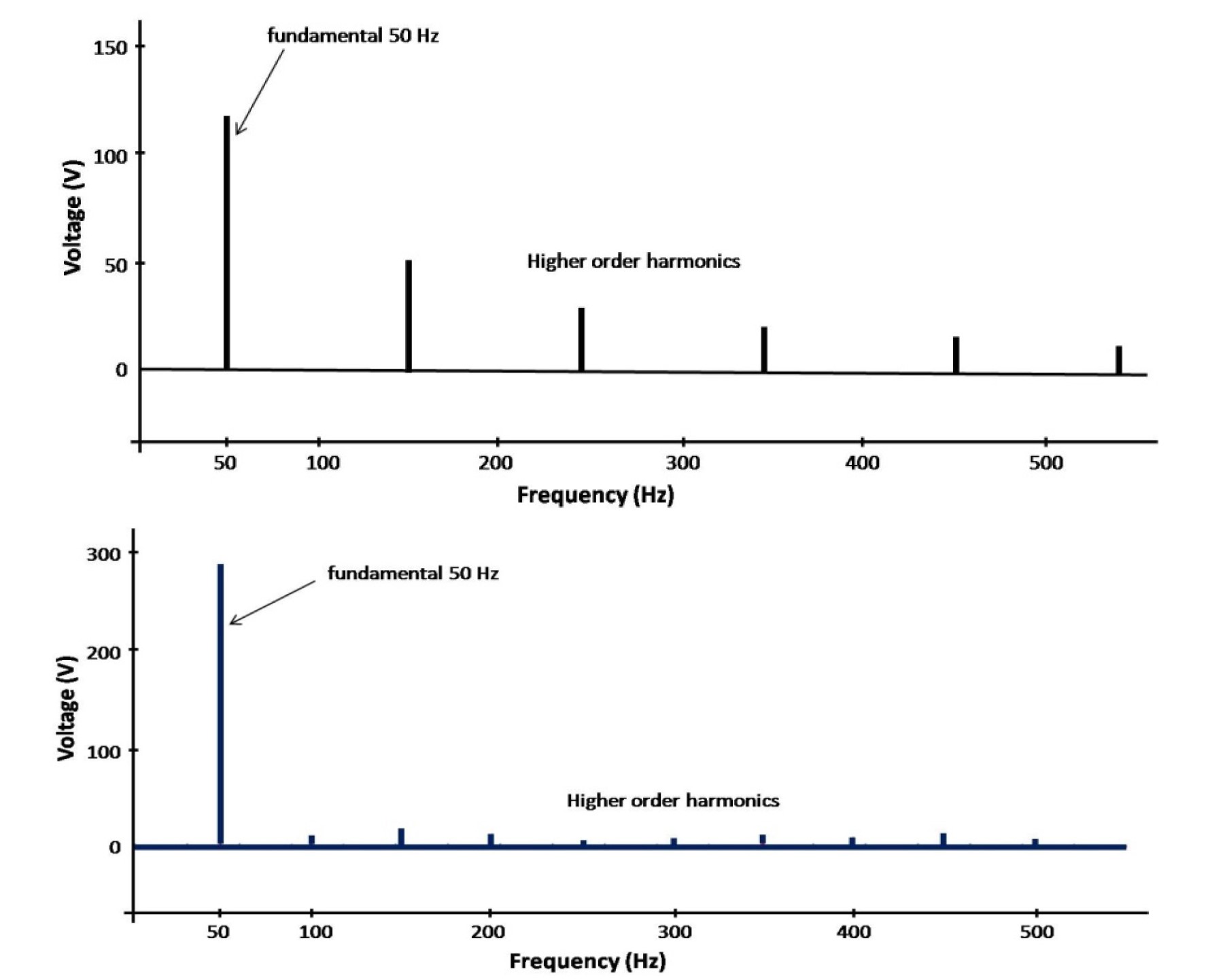
Modified sine wave inverters can provide a cost-effective solution for many applications. This design can also be referred to as a ‘modified square wave’ inverter since the waveform is a square wave that sits at zero volts for a period of time to try and approximate the energy transfer function of a sine wave. If the waveform has positive and negative peak values for half of the cycle time, the peak-to-RMS voltage ratio is the same as a sine wave. However, both square wave and modified sine wave inverters have high levels of total harmonic distortion (THD). The THD for a modified sine wave inverter can be 30%, better than that of a square wave inverter, but still quite high.
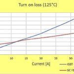
High levels of THD make square wave and modified square inverters unsuitable for powering many devices. In addition, the THD makes these inverters less efficient than pure sine wave inverters (Figure 2). The presence of harmonics can also reduce the efficiency of powered equipment. For example, many ac motors will operate with modified sine wave power but at about 20% lower efficiency compared with sine wave power.
Square wave and modified square wave inverters can be found in low-power consumer applications such as portable PV chargers, where cost is important. For medium-sized and larger green energy installations, pure sine wave inverters deliver higher efficiencies and produce the equivalent utility-grade power. Sine wave inverters can be designed in several ways. For example, the input low voltage DC power can be converted to a higher DC voltage that is then converted to a sinewave using pulse width modulation (PWM) techniques. This approach is common in higher power PV inverters and does not require an output transformer.
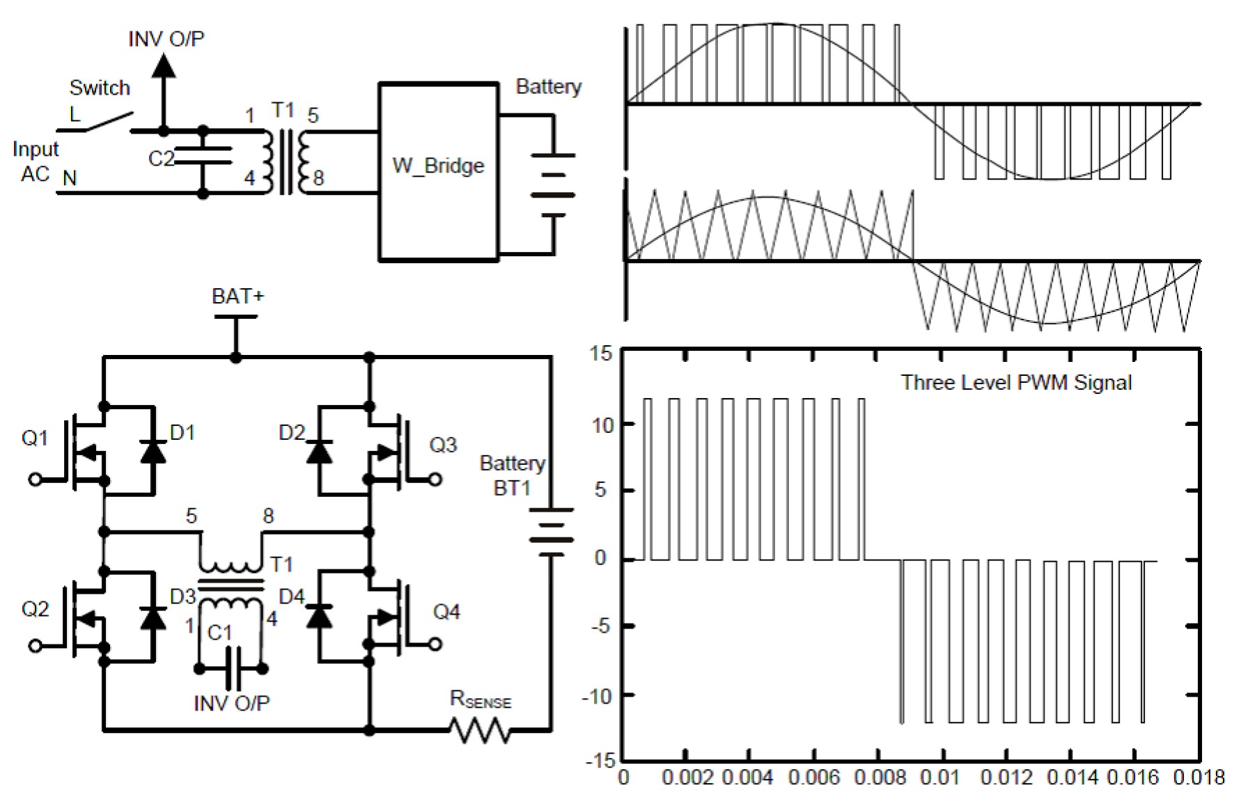
Residential sized PV inverters often convert the low-voltage DC input from the PV string directly to AC which is then boosted to grid voltage through a transformer (Figure 3). In a typical design, a full bridge topology is used to chop the battery voltage into AC using a high-frequency pulse width modulator (PWM). The resulting low-voltage AC power is fed through a 50/60 Hz transformer (depending on the desired output frequency) to produce 120 or 240 Vac power. The addition of a capacitor filter eliminates most harmonics and produces ‘pure’ sine wave AC power. Both utility-scale and residential-scale sine wave inverters often include the option of charging backup batteries when the PV energy is not needed to power system loads. At night, or other times when PV power is not available, the inverter can use the stored energy in the battery to power system loads.
PV inverter system architectures
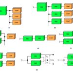
PV system size can vary from a single module to a string of modules or multiple strings. The size and architecture of the PV array determine the optimal PV inverter system architecture. There are several common PV inverter system architectures, including:
- Central PV inverter
- String PV inverter
- Multi-string PV inverter
- AC module PV inverter
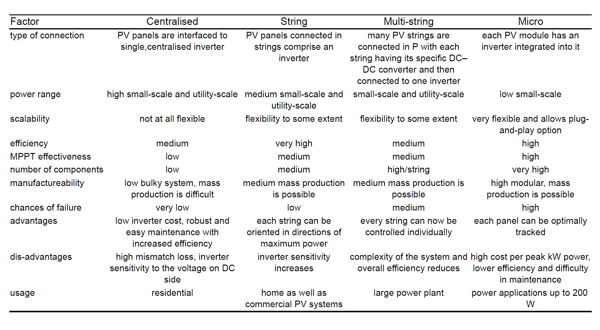
In a centralized architecture, a large number of PV modules are connected to a single inverter. The PV modules can be connected in series, parallel, or series-parallel to deliver the needed voltage for the overall system. A centralized architecture can be cost-effective for high-power installations. One challenge with a centralized approach is the complexity of implementing maximum power point tracking (MPPT) across the various PV modules. In an installation with many PV modules, different modules can experience varying irradiation, producing varying outputs. That can make it difficult to identify the precise operating point to deliver the maximum power from the array. In some cases, dc-dc converters are placed on each PV module to isolate the various modules and extract maximum power. While that can be effective, it adds significantly to overall system costs.
One possible solution is to use a string architecture where each PV string has its own inverter. While blocking diodes are needed to isolate the PV modules in a centralized architecture, no blocking diodes are used in a string configuration. MPPT implementation is simpler compared with a centralized architecture. String architectures are often found in medium-power (to about 10kW) installations such as residential PV systems.
A combination of central and string architectures produces a multi-string configuration where PV strings are connected in parallel. Each string has a dedicated dc-dc converter to deliver maximum power point operation, and the array of dc-dc converters feeds into a single centralized inverter. Multi-string architectures can be cost-effective for residential and commercial installations between 10 and 40 kW.
In a micro inverter architecture, each PV module has a dedicated inverter. Individual micro inverters are typically limited to about 300W, depending on the output of the PV module. Using an inverter on each PV module eliminates any concern with MPPT and can result in a scalable and easily expandable installation. The operational benefits of this approach come with an increased cost compared with centralized and string architectures.
PV inverter and system standards
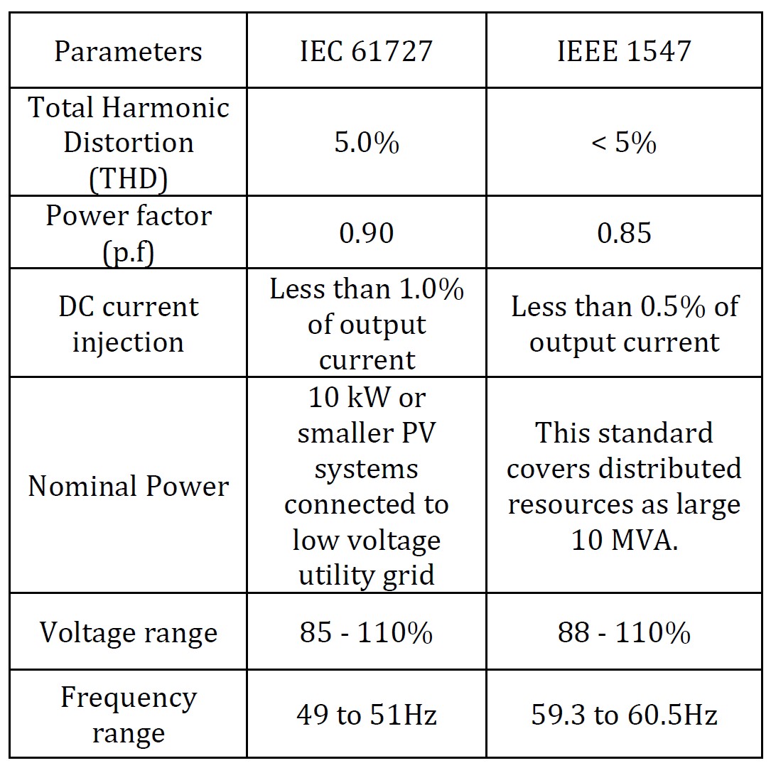
There are many international, regional, and national standards related to PV installations. The following provides a summary of a few of the more important standards. One common requirement is for anti-islanding performance for grid-connected PV inverters. If the grid goes down and the PV inverter continues to feed power onto the grid, it can result in serious safety hazards for personnel working on the grid. In instances where the grid goes down, IEC 61727 and IEEE 1547 require grid-connected inverters to disconnect from the grid in 2 seconds or less automatically. IEC 61727 is targeted for smaller systems, while IEEE 1547 also applies to larger installations. The technical performance requirements of IEEE 1547 are generally more restrictive (Table 2).
Standards have been established for a wide variety of PV inverter characteristics, including expected nameplate information, how to measure inverter efficiency, safe operation of inverters, general standards for inverters connected to independent power systems, and more, including:
- EN 50524 (Data Sheet and Name Plate for Photovoltaic Inverters) describes datasheet and nameplate information for photovoltaic inverters to provide the minimum required to configure a safe and optimal system photovoltaic inverters.
- EN 50530 (Overall Efficiency of Photovoltaic Inverters) – procedure for measuring the accuracy of both static and dynamic MPPT of inverters. It also combines the static MPPT efficiency and conversion efficiency to determine the overall inverter efficiency.
- IEC 61683 (Power conditioners – Procedure for measuring efficiency) – guidelines for measuring the efficiency of power conditioners used in stand-alone and utility-interactive photovoltaic systems; efficiency is calculated from a direct measurement of input and output power.
- IEC 62109-1 (Safety of Power Converters for Use in Photovoltaic Power Systems – Part 1: General Requirements) – generally applies to the power conversion equipment (PCE) for use in PV systems where a uniform level of safety is necessary and defines minimum requirements for protection against electric shock, excessive energy levels, fire, and mechanical and other hazards.
- IEC 62109-2 (Safety of Power Converters for Use in Photovoltaic Power Systems – Part 2: Particular Requirements for Inverters) – covers specific safety requirements for PV inverters, including grid-interactive, stand-alone of multiple mode inverters used individually or in various array configurations, including the use of backup batteries or other forms of energy storage.
- UL 1741 (Inverters, Converters, Controllers and Interconnection System Equipment for Use with Distributed Energy Resources) – covers inverters, converters, charge controllers, and interconnection system equipment in stand-alone or grid-connected power systems. In the case of grid-interactive installations, UL 1741 is intended to supplement and be used in conjunction with IEEE 1547 and IEEE 1547.1.
Summary
Most green energy installations rely on efficient and cost-effective power inverters. The most-common inverter types are modified sine wave and pure sine wave. Square wave inverters are lower in cost but are relegated to low power inverters for consumer use. In addition to the output waveform, inverters can be classified by the overall system architecture. In ascending scale from low-power to high-power systems, inverter architectures include micro, string, multi-string and centralized. Whenever inverters are used to deliver AC power, numerous international standards cover inverter operation, performance measurements, safety, and installations.
References
800VA Pure Sine Wave Inverter’s Reference Design, Texas Instruments
Critical review on various inverter topologies for PV system architectures, IET Renewable Power Generation
Electric Energy Management and Engineering in Solar Cell System, Intech
Inverter Topologies for Grid Connected Photovoltaic Systems: International Research Journal of Engineering and Technology
Solar inverter certifications: UL 1741, IEC 61683, IEC 62109, Sinovoltaics