You may or may not have thought about group delays in your electronics signal processing chain, but it is almost certainly there. It may not matter that it is there, but you need to be aware just in case. One way in which it might affect you is if you are sampling a signal. The time you sample the signal will not necessarily be the time of the actual event before signal processing. Take a simple 4 pole Butterworth filter as an example. With a 1kHz bandwidth you will see a group delay response below.

So, even well below the cut-off frequency there is an almost constant group delay of around 416us. A group delay can be considered as a varying phase shift so plotting that results in:
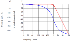
As this is on a log-lin scale it is not obvious what is happening. Changing the x-axis to a linear scale makes it clearer. Now you can see that in the area of constant group delay the phase actually changes linearly with frequency as would be expected. If you double the frequency you would double the phase shift from a fixed time delay.
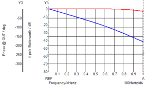
That is to be expected – if you double the frequency the phase shift doubles.
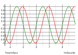
So, why should you care about this delay or phase shift? Well, if you are monitoring a constant sine wave then it probably won’t matter much. A signal well below the cut-off frequency will simply be delayed by 416us but otherwise be fine, as illustrated below for a 500Hz sine wave.
However, if you were sampling a signal that was changing and were relying on knowing the time of your sample then you need to know that the signal you are sampling has been delayed, in this case by 416us. If your sample time was based on some signal you generated and you expecting to be sample a signal response then again you need to take into account the delay. One example might be measuring the response of a system with a modulated light source. You would know when the light source was turned on and off and may have an almost instant optical system response time, but the time you need to sample the returned signal would be subject to your delays. If you are sampling at a high rate then the delay won’t necessarily matter but if you are taking a limited number of samples and expecting to be able to predict when the peak signal will occur then you will need to take the delay into account.
The effect of these phase shifts can be significant with fast signals. If you put a 100Hz square wave through your 1kHz 4-pole Butterworth filter, you will get some overshoot:
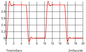
This is over 11% overshoot which is quite significant. If you look up various filter types in your electronics books then you will find that is exactly what is to be expected from a 4 pole Butterworth filter. Higher order filters have higher overshoot and high ripple Chebyshev filters have even higher overshoot. For example, a 4 pole 2dB ripple Chebyshev will have 28% overshoot. This overshoot also means the signal takes longer to stabilize so if you were hoping to sample the signal and get an accurate value, you need to wait longer until it has stabilized.
So, why do we get this overshoot and what is the solution? The cause is the delay through the filter and the fact that all frequencies are not delayed by the same time. If all frequencies were delayed by the same time (and the amplitude was unchanged) then the square wave wouldn’t have any overshoot. However, if you perform a Fourier transform on your waveform you will find that the sine harmonics that exist to make up a square wave have no limit. The amplitude of the harmonics only reduce quite slowly as frequency increases. So, for a 100Hz square wave the fundamental is a 100Hz sine wave. The third harmonic component is one-third of the fundamental. The fifth harmonic amplitude is one fifth of the fundamental. So, even by the 99th harmonic you still have sine component which is 1% of the fundamental. So, a filter with a cut-off frequency considerably higher than the input square wave will still have an effect on higher harmonics and so distorts the resulting signal, causing the overshoot. The reduced amplitude of the higher harmonics will also distort the signal.
So, if the Butterworth filter has a constant group delay at low frequencies, what is the cause? It is the imperfect phase response as you approach the passband. If you look closer at the earlier graph showing phase against frequency on a linear scale, you will see it is not quite a straight line. This can be seen below when compared with a Bessel filter.
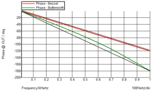
Straight black lines have been drawn next to each of the phase curves so it is easier to see that the Butterworth filter actually has a non-linear phase shift with frequency near the cut-off frequency whereas the Bessel filter is almost a straight line. The benefits of the Bessel filter on overshoot can be shown from a transient plot with a square wave input.
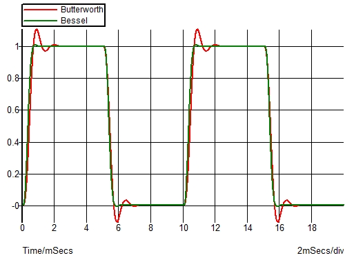
There is still a small overshoot on the Bessel filter of around 0.8% – but considerably less than the 11% of the Butterworth filter. The phase response of the Bessel filter deviates from a straight line above the cut-off frequency but the amplitude of the higher frequency components is lower above cut-off so the effect on overshoot is less.


Great informative article, has helped to clear up one doubt I have had since starting to learn about filters regarding Bessel vs Butterworth filters, wasn’t aware of the difference in overshoot. Thanks.
(Spot the mistake: the last paragraph reads “There is still a small overshoot on the Bessel filter of around 0.8% – but considerably less than the 11% of the Bessel filter.”)
Thanks. I would sack my proof reader but that is myself!