The logic analyzer is an advanced instrument that displays the content of numerous digital data streams simultaneously and in various formats. It is continuously evolving. Manufacturers are offering new and ever more advanced features that facilitate with great precision design, debugging and repair of digital systems.
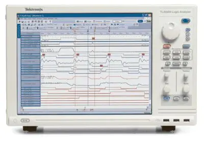
Tektronix TLA6400 real-time logic analyzer display.
While the oscilloscope remains relevant in the digital domain, the fact is that digital pulses are analog waveforms notwithstanding their abrupt rise and fall times. Mixed-signal and mixed domain oscilloscopes have internal logic analyzers typically with 16 or so channels. They can trigger on digital as well as analog signals, capturing and displaying relevant information.
The logic analyzer goes farther. It can capture state-mode data, and with a high channel count, it has greater analytic depth and insight. The oscilloscope, in contrast, has high sample rate and bandwidth, permitting it to capture and display a greater number of data points over a longer time period. Compared to the logic analyzer, amplitude and frequency can be displayed in greater detail and measured more accurately. The user can see signal transitions, transient events and temporally small increments. The oscilloscope can better capture details including ringing, overshoot, rising edge roll-off, and other periodic aberrations.

Digital oscilloscopes and logic analyzers are both based on sampling techniques. Signal measurements are transformed into digital value by a high-speed analog-to-digital converter and stored in memory at regular intervals defined by the instrument sampling clock. But a logic analyzer displays signals as binary values, according to whether the measured voltage is above or below a conventional voltage level called threshold value.
Digital signals are far more immune to noise than are the corresponding analog waveforms but in the interest of electronic integrity, it is important to know the precise anatomy of digital pulses to ensure that distortion does not become an issue to the extent that the bit error rate is impacted. Only the oscilloscope can display signal amplitude, rise and fall time and general analog details in its characteristic resolution.
You may wonder how the logic analyzer can have a high channel count, considering the extent to which oscilloscope channels (typically two or four, sometimes more) are such a prominent factor in the final cost of the instrument. The answer is that the signal in a logic analyzer or in the digital input in an oscilloscope is applied more or less directly to the memory and processor. Separate clocks and ADCs, which can be bandwidth bottlenecks, are not needed. The numerous channels are merely separate inputs, although separate probes are required.
Contemporary logic analyzers in the same unit perform two separate functions. In the timing analysis mode, they sample and time with a clock the digital data stream as applied to the individual channels. The samples are first stored in memory and then displayed as data in timing waveforms. This method is known as asynchronous measurement. It measures the time relating only to each signal, looking for glitches, and it reveals hardware problems to the user.
 In the logic-state-analysis mode, the logic analyzer makes use of clock signals that come from within the equipment under investigation. Data is sampled and stored in memory as it is synchronized within the connected equipment. A binary or hexadecimal display is created. This method is an example of synchronous measurement and, in contrast to the logic timing analysis mode, it addresses software problems.
In the state analysis mode, data is displayed as a list or graph. In the timing analysis mode, the user sees a logic timing diagram potentially consisting of input from the full number of connected channels.
Rather than measuring analog signals in great detail like an oscilloscope, the logic analyzer detects logic threshold levels. After an input is sampled, what is stored is a 0 or 1. The high channel count in a logic analyzer together with extensive features in the instrument facilitate both design verification and debugging.
The logic analysis mode acquires data in accordance with conditions specified by the user. The instrument acquires information in response to sophisticated triggering options, which filter out irrelevant data.
Carefully engineered probes are capable of connecting to closely spaced traces and terminals in today’s increasingly dense printed circuit boards. Captured data may be interpreted in the context of processor instructions and correlated to source code.
Time base in an oscilloscope becomes capture rate in a logic analyzer. Other terminology is common to both instruments, and word meanings overlap in different ways. In a logic analyzer, “sample,” “acquire” and “capture” are closely related. The two basic types of acquisition are:
•Timing Acquisition, which refers to the event in which data is sampled in accordance with a clock within the logic analyzer. Resolution depends upon the speed at which data is sampled. A faster rate equates to higher resolution. Timing is not relative to the equipment under investigation, but strictly to the logic analyzer.
•State Acquisition refers to the condition of the signal at a given point in time following a transition. The acquisition may be clocked from within the logic analyzer, within the equipment under investigation or external to both. The logic analyzer samples only a validating signal, discarding irrelevant events.
Triggering plays a unique role in the logic analyzer. The MDO3000 oscilloscope triggering menu options enable the user to control triggering type, source, coupling (ac or dc), slope (rising edge, falling edge or both), level and mode, which can be automatic, manual or holdoff (delayed after trigger event by a user-determined amount of time).
In the logic analyzer, triggering plays a different role. Its purpose is not to synchronize waveforms as in the oscilloscope so they can be displayed coherently, but instead in the logic analyzer to determine the data that is to be captured. The user is able to set the triggering agenda based on events in the digital data stream. Such an event can consist of a transition, glitch, or the appearance of a particular signal such as Enable. Another possibility could be a specified signal transition.
A triggering event in a logic analyzer may consist of specific binary-conveyed words, events that happen between definite high and low values, a given number of events reckoned by a counter, an external reset, a glitch, elapsed time, or an analog event picked up from a separately-connected oscilloscope. A process can be repeated any number of times as the user stipulates additional triggering events, all the time narrowing in on problematic elements.
State and timing acquisitions can be displayed simultaneously in a logic analyzer in the same manner that time and frequency domain representations of an analog signal can be displayed in a mixed domain oscilloscope. Juxtaposing state and timing acquisitions in a logic analyzer can involve some elaborate probing, especially when the signal source is a dense printed circuit board. Some test instruments require double probing while in others a single probe conveys both data streams. Double probing can also adversely affect impedance matching, causing increasing distortion at high data rates.
In choosing a logic analyzer, sample rate and memory depth are critical specifications. The number of channels required is based on the equipment to be analyzed. Additionally you have to allow for external requirements including clock and enable inputs. As for memory depth, the total acquisition time decreases as the sample rate increase, so you have to know the highest clock and actual operating rate of equipment likely to be investigated.
In the interest of capturing errors and underlying faults, acquiring more samples is essential. The logic analyzer operator can place the trigger at any chosen location in memory. This decision influences the way that the acquired data can be interpreted so as to shed light on the inner workings of the digital source. Where the trigger is placed is crucial. If the instrument triggers on a given anomaly, the user can gain insight by analyzing the data that precedes or follows the trigger event. Pre-trigger and post-trigger information will enable the user to draw conclusions and eventually locate the fault within hardware (timing analysis mode) or software (logic state analysis mode).
Long-term bus activity can be ascertained by looking at a long record length, which is made available in contemporary logic analyzers. We can capture data at high GHz rates from data developed across hundreds of channels. Increased speed and resolution are making the logic analyzer a cutting-edge instrument that works well in conjunction with the relatively traditional digital storage oscilloscope.

Leave a Reply
You must be logged in to post a comment.