
We often discuss signal integrity in relation to digital data and communications — trying to ensure a high-speed digital signal isn’t corrupted during transmission— but analog signal integrity is also important. It could be simply trying to preserve the signal quality and accuracy within a PCB, or it could also cover the problem of transmitting an analog signal a few feet or even miles.
One solution to the problem of long distances is to digitize the signal. Preserving the integrity of a digital signal is not as difficult as preserving an analog one. I have done this in the past where I needed to send audio several miles using fiber optics. In that case, the signal was transmitted digitally and turned back into an analog signal at the receiving end. The alternative is to try to preserve the integrity of the analog signal, which over large distances can be difficult. Over long distances, one problem you will face is that the two ends of the circuit can be at different and indeterminate voltages so some form of isolation would be required such as optoisolation.
Simple connections between PCBs in a system can often be managed by using screened cable and coaxial connectors. Another alternative is a differential twisted pair cable. While they are used for digital transmission such as wired networks (LAN), they are not necessarily that good at preserving the integrity of analog signals due to the possibility of interference. Adding a screen to a differential pair, however, can make quite a difference. The other advantage of differential signals is that you can design in some tolerance to the two ends of the system at different voltages. That will not be good enough if the two ends of the cable are hundreds of yards apart, but should work with a system where the two ends are reasonably close.
With any purely analog signal transmission, you must consider the drive impedance, cable capacitance and cable and load impedance. These will limit the bandwidth of the connection as well as the accuracy. If the source impedance is too high or the load resistance too low then cable resistance will affect the accuracy. A long established method round the accuracy problem is to use a current rather than a voltage to transmit the signal. The 4-20mA current loop is the common “standard”. Any voltage drops in the cable will not affect the accuracy because the signal is a current, not a voltage. A well-designed system will also tolerate some voltage differences between the two ends of the 4-20mA loop. n fact, there needs to be a voltage somewhere to generate the current. This voltage is usually at the receiving end of the interface. Speed is not necessarily great and such current loops are chosen more as a process control solution rather than a means to transmit any sort of high-speed signals.
There are chips to help make a 4-20mA transmitter such as the XTR115 from Texas Instruments. These are fairly old devices dating back to the Burr-Brown days, but that doesn’t matter if it does what you want.
If you want to transmit a value that is already in digital form, then you could use a DAC with 4-20mA output such as the Texas Instruments DAC161S997. It depends on what you will do with the data at the receiving end. But if the data is already digital, then I would transmit it digitally rather than using a 4-20mA loop — unless the 4-20mA receiver is not something you can change.
Opto-isolation need not only be for a signal digitized by an analog to digital converter (ADC), it could also be used where the signal is encoded using pulse width modulation for example. Another technique you can use is voltage-to-frequency conversion. This technique allows you to transmit a signal across an isolation barrier such as a transformer or capacitor, as well as optoisolation. The frequency will be unaffected by voltage drops and signal levels provided you have enough signal to work with at the receiving end. However, you do need to consider the bandwidth you require from your final signal.
There are devices available for helping design an isolated analog signal transmission system although some are old, expensive devices which require +/-15V power supplies. These include the Analog Devices AD215 or Texas Instruments ISO124. The accuracy of some of them isn’t great, so check if you are planning to use one that it will meet your requirements.
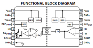
More modern and cheaper is the Analog Devices ADuM3190 which can work from 3V to 20V. It is intended for isolated error feedback in power supplies so it is not considered a general purpose device.
Another modern, reasonably priced device is the Texas Instruments AMC1100 which is intended for isolated current shunt measurements.
If you want to digitize the signal but also isolate it, then you could look at isolated ADCs such as the Analog Devices AD7405. You could, of course, make your own isolated ADC by adding some digital isolation to the outputs of an ADC — preferably one with serial outputs in order to minimize the number of digital channels that need isolating. The use of a serial interface will limit the overall sampling rate, however, but a parallel interface will increase complexity significantly. There are high-speed serial interface chips available so even digital video can be transmitted with optoisolation as long as you have the right optoisolators. Finding very high-speed optoisolators can be tricky; it is easier to find the components for very high-speed fiber-optic links. The Avago HCPL-0900 series optoisolators are suitable for up to 100Mbaud (50MHz), but most optoisolators are considerably slower.
Related resources:
The intricacies of signal integrity in high-speed communications, Texas Instruments Analog Applications Journal




Leave a Reply
You must be logged in to post a comment.