Spectrum analyzers let you see how distortion can affect transmitted RF signals.
A transmitted signal’s power output and spectral purity needs testing to ensure that it meets the overall system requirements. The wireless spectrum is filled with many signals and each signal must stay within its assigned channel. In Measure power in complex RF signals, we looked at broadband and narrow-band power measurements. Spectral purity measurements require narrow-band measurement, and you need to use a frequency-selective instrument such as a spectrum analyzer. Broadband power meters are not sufficient.
Channel power
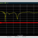
The channel Power of an RF signal is just that: the total power within the specified channel bandwidth. Figure 1 shows the channel power of a typical digitally modulated signal. Note that this signal is typical of modern digital modulation: the spectrum has a broad, somewhat noisy shape, with no distinct spectral lines. The channel is 5 MHz wide and the signal occupies most of that frequency span, falling off as it approaches the edge of the channel. The spectrum analyzer integrates all the power in the prescribed channel and displays the result as -20.86 dBm.
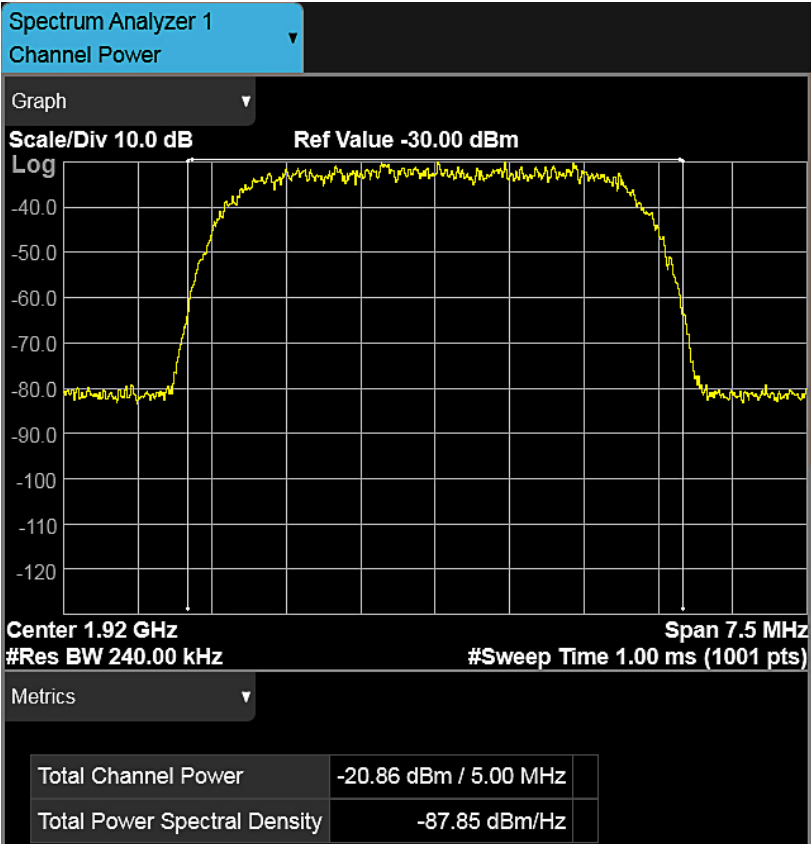
Figure 1. A channel power measurement of a digital wireless signal shows if any power falls outside the
channel frequency band. Image: Keysight Technologies
Occupied bandwidth
The occupied bandwidth of an RF signal describes how wide the signal is in the frequency domain, based on a percent of the total power in the signal. For example, a common specification for occupied bandwidth is the frequency range that contains 99% of the transmitted power.
Adjacent channel power
It is important that an RF signal stay within its intended frequency space (channel). When an RF signal spills over into adjacent channels, it causes interference to the other wireless channels and degrades the system performance. No signal is perfect, so there is going to be a small amount of energy that affects the adjacent channels.
Adjacent-channel power is the amount of power that leaks into the adjacent channels. This may be specified in terms of absolute power or, more commonly, as a ratio of the adjacent channel power to the main channel power, called adjacent channel power ratio (ACPR) or adjacent channel leakage ratio (ACLR). We can express this ratio in decibels using this formula:
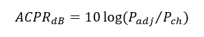 Where Pch is the main channel power and Padj is the power in the adjacent channel.
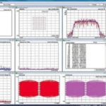
Figure 2 shows an ACPR measurement, with the main channel in the center of the display and two adjacent channels on either side. The channel power measurement bounces around at -4 dBm. The two close-in adjacent channels are showing -65 dBm and -70 dBm, which correspond to ACPR of -61 dBc and -66 dBc where dBc indicates dB relative to the carrier or channel power. The measurement is noisy and the results vary.
Figure 2. Adjacent Channel Power measurement of a digitally modulated signal shows how out-of-band-energy insreases as the freqyency gets close to the channel of interest.
Image: Keysight Technologies
Note that the two close-in channels have an ACPR that is approximately 5 dB worse than the outer channels. In Figure 2, you can see that the power in the adjacent channels increases slightly as it approaches the main channel.
Amplifier nonlinearity
As engineers push for maximum output power and amplifier efficiency, nonlinearities in the amplifier can cause the main channel to leak into the adjacent channels. This is sometimes called spectral leakage and is a key contributor to degraded ACPR.
Nonlinearities cause distortion that can occur in a variety of ways in an amplifier. Harmonic distortion is common but only affects frequencies at integer multiples of the main carrier. These frequencies are normally out of band and are often removed with a lowpass filter.
The classic model for intermodulation distortion produces distortion products at these frequencies, where n and m are integers [Ref 4].
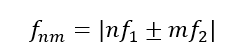 Third-order intermodulation distortion can be particularly troublesome because it creates distortion products “close-in” to the main channel. As an example, consider two frequencies, f1 and f2, inside the main channel.
The frequency of one of the third-order intermodulation products is given by:
![]() As an example, suppose f1 = 1.922 GHz and f2 = 1.918 GHz, the f21 distortion product will be 1.926 GHz, which is relatively close to the original frequency pair. Depending on the exact frequencies and the channel spacing, the distortion product can land inside the main channel or in one of the adjacent channels.
As an example, suppose f1 = 1.922 GHz and f2 = 1.918 GHz, the f21 distortion product will be 1.926 GHz, which is relatively close to the original frequency pair. Depending on the exact frequencies and the channel spacing, the distortion product can land inside the main channel or in one of the adjacent channels.
Amplifier test
You can measure a transmitted signal’s ACPR to determine the overall performance of that transmitter. You can also measure the individual components inside the transmitter or RF system.
Figure 3 shows how a signal generator and spectrum analyzer are used to check the performance of a power amplifier. The signal generator supplies a known-good modulated RF signal (to some specification) and the spectrum analyzer measures the ACPR to see how much the ACPR degrades at the amplifier output. Any degradation found is due to distortion introduced by the amplifier.
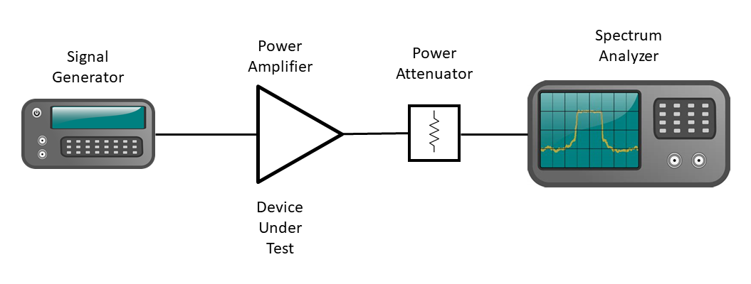
Figure 3. The performance of an amplifier can be determined by supplying a known good signal from a signal generator and measuring the amplifier output using a spectrum analyzer.
The power attenuator reduces the signal level from the amplifier to a level that the spectrum analyzer can handle. Of course, the spectrum analyzer can measure other parameters of the signal that can help you gauge an amplifier’s overall performance.
Summary
Evaluating the spectral content of a transmitted signal requires a narrowband measurement. Broadband power meters can tell us the power of the signal but cannot measure the finer details. Adjacent channel power is one of the key measurements for quantifying the quality of a signal and power amplifier performance.
References
1. “RF power measurement, Part 1: Why and where,” Bill Schweber, EE World Online, April 2018. https://www.eeworldonline.com/rf-power-measurement-part-1-why-and-where-faq/.
2. “RF power measurement, Part 2: What and how,” Bill Schweber, EE World Online, April 2018. https://www.eeworldonline.com/rf-power-measurement-part-2-what-and-how-faq/.
3. “Making Fast and Accurate Power Measurements with Absolute Confidence,” Application Note, Keysight Technologies, Publication Number 5992-2906, July, 2021. https://www.keysight.com/us/en/assets/7018-06123/application-notes/5992-2906.pdf.
4. Spectrum and Network Measurements, 2nd ed., Robert A. Witte, Chapter 7, Distortion Measurements, SciTech Publishing, 2014.
5. “Techniques for Precise Power Measurements in the Field,” Application Note, Keysight Technologies, Publication Number 5991-0423EN, 2015.
https://www.keysight.com/us/en/assets/7018-03481/application-notes/5991-0423.pdf.
 Bob Witte is President of Signal Blue LLC, a technology consulting company. Bob has held many positions in R&D, technology planning, strategic planning, and manufacturing for Keysight Technologies, Agilent Technologies and Hewlett-Packard Company. Inside, he is just an engineer that loves to see innovative products solve real customer problems. Bob is the author of two books on test and measurement instrumentation: Electronic Test Instruments (2nd Edition) and Spectrum and Network Measurements (2nd Edition).