The usual rationale for a filter in electronic circuitry is to reject unwanted portions of a spectrum or at least reduce their amplitudes to acceptable levels without attenuating the desired frequency or range of frequencies.
In some situations, active filters are needed to perform this function, and often they are less expensive than alternate solutions involving clunky old inductors. In regard to their intended purpose, electronic filters are classified according to the specific part(s) of the spectrum that they pass or reject. The words are self-evident: high-pass, low-pass, band-pass, band-stop (including band rejection and notch) and all-pass.
Electronic filters can be passive or active, sampled (discrete time) or continuous time, linear or non-linear, and they can also be characterized as infinite impulse response (IIR) and finite impulse response (FIR). Most analog electronic filters are the IIR variety, whereas digital filters may fall into either category. IIR filters have an impulse response that never equals zero. An FIR filter, in contrast, actually diminishes to zero after a definite time interval. If the filter contains only resistors and capacitors, inductors or both, it is most likely an IIR filter. But if the filter contains a tapped delay line without incorporating feedback, it is the FIR variety.
 In theory, analog filters with capacitors and/or inductors never become totally de-energized and, for this reason, may be said to have memory, whereas a digital filter with a tapped delay line characteristically goes to zero because the original impulse reaches the end of the tapped delay line and ceases to exist. The concept of a memory is not applicable.
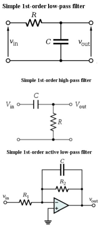
Passive filters are built using only passive components – resistors, capacitors and inductors. This tends to give them good high-frequency performance and, compared to active filters, higher voltage and current tolerance as well as reduced noise output. In a low-pass passive filter, capacitor(s) are placed in parallel with input and output, and the inductor (if any) sits in series. In a high-pass filter, the capacitor(s) are placed in series with input and output, and the inductor (if any) sits in parallel.
Active filters have some definite advantages over passive versions, including the ability to provide signal gain, higher input and lower output impedances, no need for buffer amplifiers, and less dependency on inductors, which add expense.
Most electronic filters are linear. In analog electronics, this means that a time-varying input signal will produce an output that is also time-varying and is subject to one or more factors but is not exponentially related. The critical aspect is frequency response, typified by transfer function, H(ω).
A filter’s frequency domain activity is defined mathematically as its transfer function. It is the ratio of the Laplace transforms of output and input signals. The voltage transfer function of a filter is just H = VOUT/VIN where V denotes the signal voltage.
When considering input and output voltage, this transfer function defines the behavior of the filter, especially when input (and therefore output) is a sine wave. The amplitude of the transfer function as a function of frequency can be displayed in an oscilloscope or spectrum analyzer in the frequency domain. The display conveys the gain at each frequency so that a determination can be made of the amplitude response or, as it is known in audio applications, the frequency response.
What defines an active filter is its use of one or more active components such as an operational amplifier. The addition of an amplifier, typically with negative feedback, substantially changes the behavior of a filter, improving its stability and eliminating expensive inductors. Moreover, an active filter, having high input and low output impedances, makes for more efficient interaction with the preceding and following stages. The active filter itself is unaffected by excessive loading.
Another advantage of the active filter is that certain parameters can be altered using inexpensive variable resisters. Q (quality factor) and the tuned frequency can be easily adjusted. In electrical systems, of which the active filter is an example, Q represents the effect of electrical resistance, so this may be easily adjusted. Higher Q would manifest as a sharper peak, in a spectrum analyzer or oscilloscope in FFT mode appearing as a narrower peak. There is less bandwidth, which in a filter at normal frequencies is a good quality. The downside, however, is that with limited bandwidth, active filters have difficulty in a high-frequency environment. Also, amplifier stages have limited power-handling capability.
Transfer functions in active filters are the same as in passive filters: high-pass, low-pass, band-pass and notch. The principle types of active filters are:
• Sallen-Key and voltage-controlled voltage-source (VCVS) filters, incorporating unity-gain amplifiers with nearly infinite input impedance and zero output impedance. A variation on VCVS is the Sallen-Key active filter that uses a pure buffer with unity (0 dB) gain. Both of these filters typically employ op-amps.
• State variable and biquadratic filters, consisting of one or more integrators in a feedback configuration.
• Dual-amplifier band-pass filters.
• Wien Notch filters.
• Multiple feedback filters, with a transfer function having two additional poles.
• Flieg filters, having two op-amps and superior frequency controllability.
• Akerberg Mossberg filters, noted for complete control over gain and frequency.
Active filters with op-amps are capable of duplicating any type of passive filter behavior unencumbered by inductors, nonlinearity, susceptibility to magnetic pickup of interference, and distributed winding capacitance. Electronic tunability is a valuable asset.
Another subtype of active filter is the switched capacitor filter. MOSFET switches are incorporated, constituting a frequency-tunable resistor. An external clocking frequency is applied, resulting in precise tuning over a wide range. There are, however, two drawbacks – presence of switching noise and less dynamic range.
Filters can be described in terms of frequency-domain or time-domain qualities. Ordinarily, we think of gain as applicable to solid-state or tube amplifiers, but it is proper to speak of gain also in the context of filters, passive as well as active. In the frequency domain, the obvious thing to look for in a filter is its amplitude of output over amplitude of input, i.e. gain, relative to frequency. The portion of the spectrum that is minimally affected by the filter is the pass band. For most filters, the pass band is defined as extending to -3 dB.
Frequency domain displays in a spectrum analyzer or oscilloscope in the FFT mode also reveal phase shift of the filter’s output relative to its input. (An all-pass filter passes all frequencies equally, but it shifts the phase relationship at differing frequencies by varying phase shift as a function of frequency.)
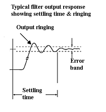
Typical ringing response as might arise when passing a step input through a low-pass filter.
Time domain display of a filter can reveal overshoot, ringing and rise and settling time. Some of these aspects of filter behavior may be harmful in specific applications. In any event, it is instructive to view in both time and frequency domain in separate channels the input and output of various filters as a selection of signals is applied.
The scope can also show the pass and cut-off qualities of the filter. To do this we measure the signal amplitude going into the filter and coming out. The cut-off frequency is the 3-dB point for many simple filter designs. The 3-dB point is where the power drops by a factor of two. Because the scope displays voltage and not power, that means the voltage should be a factor of sqrt(2) =~ 1.41 lower at this point. Half the voltage output would be 6 dB.
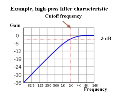
Frequencies below the cutoff frequency in a high-pass filter are not eliminated but increasingly attenuated for frequencies further below the cutoff. The cutoff frequency (sometimes also called corner frequency) defines the point at which the input power is reduced by 3 dB. The example here is of a 6 dB per decade roll off. Sharper roll-offs are of course possible.
Many digital scopes can also calculate the dB change in voltage. If the source of the filter input signal is a frequency generator, it may be practical to sweep the input frequency over, say, 10 seconds and then set the scope to a timebase that generates a full screen over 10 seconds. The result will be frequency amplitude plot for which 3 dB, 6 dB or 20 dB points should be evident.

Leave a Reply
You must be logged in to post a comment.