• Skip to primary navigation
  • Skip to main content
  • Skip to primary sidebar
  • Skip to footer

Electrical Engineering News and Products

Electronics Engineering Resources, Articles, Forums, Tear Down Videos and Technical Electronics How-To's

  • Products / Components
    • Analog ICs
    • Connectors
    • Microcontrollers
    • Power Electronics
    • Sensors
    • Test and Measurement
    • Wire / Cable
  • Applications
    • Automotive/Transportation
    • Industrial
    • IoT
    • Medical
    • Telecommunications
    • Wearables
    • Wireless
  • Resources
    • DesignFast
    • Digital Issues
    • Engineering Week
    • Oscilloscope Product Finder
    • Podcasts
    • Webinars / Digital Events
    • White Papers
    • Women in Engineering
  • Videos
    • Teschler’s Teardown Videos
    • EE Videos and Interviews
  • Learning Center
    • EE Classrooms
    • Design Guides
      • WiFi & the IOT Design Guide
      • Microcontrollers Design Guide
      • State of the Art Inductors Design Guide
    • FAQs
    • Ebooks / Tech Tips
  • EE Forums
    • EDABoard.com
    • Electro-Tech-Online.com
  • 5G

MEMS inertial accelerometer now offered in ±10 g and ±50 g ranges

April 10, 2019 By Aimee Kalnoskas Leave a Comment

Silicon Designs, Inc. announced that additional new g-ranges and end-user enhancements have been added to its Model 2227 MEMS inertial accelerometer series. 

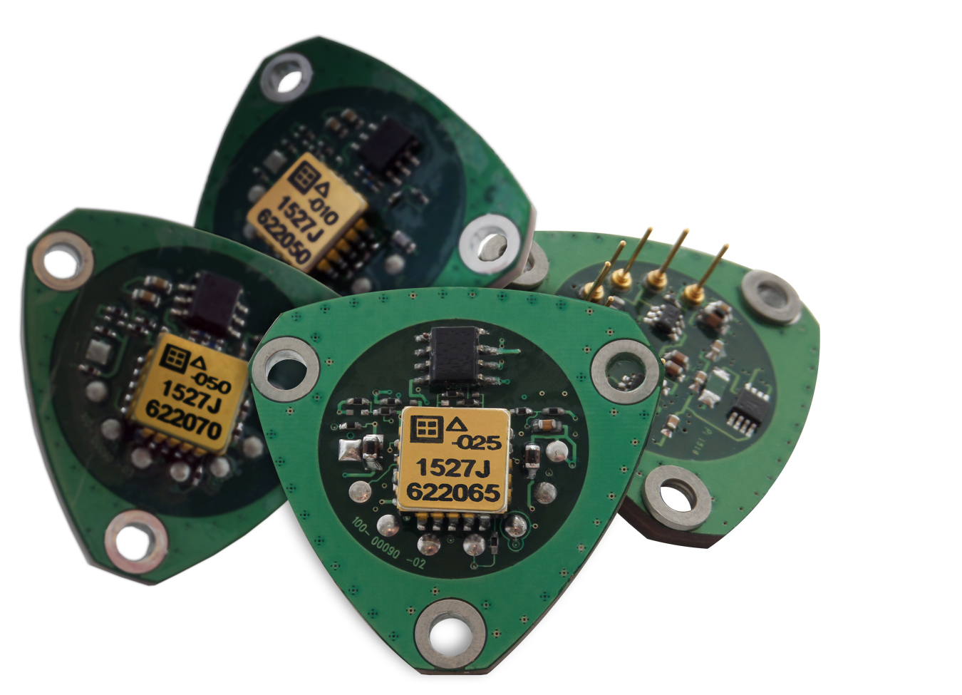
Initially launched in October 2018 as a strictly ±25-g product, the Series is now offered in both ±10 g and ±50 g ranges, respectively. Stock quantities of all three models are immediately available for customer shipment.

 In addition to its direct drop-in replacement compatibilities, in terms of industry-standard form factor and pin configuration, with traditional quartz inertial accelerometers, Model 2227 Series units now include a built-in adjustable scaling factor. The scaling factor allows an end-user to achieve greater accelerometer voltage output flexibility, at any specified g-range, of as much as 25%. 

Overall design of the Silicon Designs rugged Model 2227 Series combines two patented capacitive silicon sense elements (U.S. Patent Number 4,736,629) and a precision, custom CMOS integrated circuit. The elements and circuit are housed together within a compact, low mass, hermetically sealed LCC package. Modules are assembled on a high-temperature open printed circuit board (PCB) with a circuit that converts the MEMS accelerometer differential output voltage into a level of current directly proportional to the amount of applied acceleration. T

The resulting design allows the Series to achieve the necessary low-noise, high-stability, long-term repeatability and low power for today’s inertial navigation applications, at a competitive price point. Final testing is conducted on a temperature-tumble-system, ensuring thermal calibration parameters that simplify accelerometer use with the customer’s own real-time temperature compensation and modeling software.

DesignFast Banner version: 03eceadf

Filed Under: Analog IC Tips Tagged With: silicondesignsinc

Reader Interactions

Leave a Reply Cancel reply

You must be logged in to post a comment.

This site uses Akismet to reduce spam. Learn how your comment data is processed.

Primary Sidebar

EE Training Center Classrooms

EE Classrooms

Featured Resources

  • EE World Online Learning Center
  • CUI Devices – CUI Insights Blog
  • EE Classroom: Power Delivery
  • EE Classroom: Building Automation
  • EE Classroom: Aerospace & Defense
  • EE Classroom: Grid Infrastructure
Search Millions of Parts from Thousands of Suppliers.

Search Now!
design fast globle

R&D World Podcasts

R&D 100 Episode 7
See More >

Current Digital Issue

April 2022 Special Edition: Internet of Things Handbook

How to turn off a smart meter the hard way Potential cyber attacks have a lot of people worried thanks to the recent conflict in Ukraine. So it might be appropriate to review what happened when cybersecurity fi rm FireEye’s Mandiant team demonstrated how to infiltrate the network of a North American utility. During this…

Digital Edition Back Issues

Sponsored Content

Positioning in 5G NR – A look at the technology and related test aspects

Radar, NFC, UV Sensors, and Weather Kits are Some of the New RAKwireless Products for IoT

5G Connectors: Enabling the global 5G vision

Control EMI with I-PEX ZenShield™ Connectors

Speed-up time-to-tapeout with the Aprisa digital place-and-route system and Solido Characterization Suite

Siemens Analogue IC Design Simulation Flow

More Sponsored Content >>

RSS Current EDABoard.com discussions

  • Smallest header needed to support PCB vertically above main PCB
  • What base emitter resistors are inside Darlington
  • Simulation of resonator in HFSS
  • series connection of power audio amplifier
  • Sampling with MOS transistor and cap

RSS Current Electro-Tech-Online.com Discussions

  • software PWM
  • ASM - Enhanced 16F and long calls - how?
  • Ampro 16mm Stylist projector woes.
  • Will Header and socket hold this PCB OK?
  • Passthrough charging-simple but impossible to achieve?

Oscilloscopes Product Finder

Footer

EE World Online

EE WORLD ONLINE NETWORK

  • 5G Technology World
  • Analog IC Tips
  • Battery Power Tips
  • Connector Tips
  • DesignFast
  • EDABoard Forums
  • Electro-Tech-Online Forums
  • Engineer's Garage
  • Microcontroller Tips
  • Power Electronic Tips
  • Sensor Tips
  • Test and Measurement Tips
  • Wire & Cable Tips

EE WORLD ONLINE

  • Subscribe to our newsletter
  • Lee's teardown videos
  • Advertise with us
  • Contact us
  • About Us
Follow us on TwitterAdd us on FacebookConnect with us on LinkedIn Follow us on YouTube Add us on Instagram

Copyright © 2022 · WTWH Media LLC and its licensors. All rights reserved.
The material on this site may not be reproduced, distributed, transmitted, cached or otherwise used, except with the prior written permission of WTWH Media.

Privacy Policy