by Rudy Ramos, Mouser Electronics
In the past, factories were noisy places; in fact, noise-induced hearing loss was one of the most common occupational ailments in the USA. As the Industrial Internet of Things (IIoT) – sometimes termed Factory 4.0 – led to more electronics in factories, electromagnetic noise replaced audible noise.
As the need for process efficiency increased, factories were filled with sensors to monitor the process, reduce costs and preemptively predict failures. However, each sensor produces lots of data (“big data”), which travels through wires or across the airwaves, creating electromagnetic noise.
EMC in a Modern Factory
Wikipedia defines Electromagnetic compatibility (EMC) as the “branch of electrical engineering concerned with the unintentional generation, propagation and reception of electromagnetic (EM) energy, which may cause unwanted effects such as electromagnetic interference (EMI) or even physical damage to operational equipment.”
There are two principal concerns with EMC: generation of unwanted EM energy (emissions), and devices being affected by EM noise (susceptibility). These can be characterized by their propagation method, either conductive or radiative, giving a total of four areas to consider.
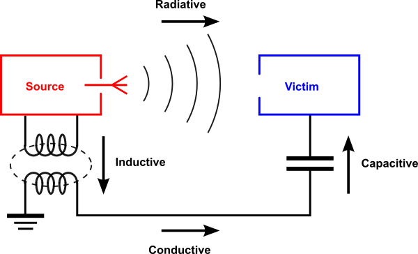
Factories are a particularly challenging environment. Often they have evolved over many years and were originally designed and built before modern low-power, low-voltage electronics existed. With the addition of hundreds or even thousands of sensors, along with computer and other communication networks, there are more devices than ever creating – and susceptible to – EMI.
Modern electronics is a long way from the heavy equipment originally found in factories. Today’s devices run on low voltages, and even a few millivolts of noise on a supply or signal line can wreak havoc with high-speed data feeds.
There are many large machines in a typical factory, all with the potential to create unacceptable levels of EMI, especially as they are turned on or off. Welding equipment, especially arc welding, is a particular challenge; radio frequency (RF) energy from welding pulses can induce voltage spikes in power and ground lines, affecting nearby electronic equipment.
Some Applicable EMC Standards
EMI can be dangerous, in some cases affecting critical radio frequencies such as those used by first responders or air traffic control, to name just two. As a result, standards for EMC and EMI have been introduced globally.
In the USA, the Federal Communications Commission (FCC) defines EMC compliance standards. Part 15 of the FCC regulations stipulates the required emissions tests that will prevent disruptive RF emissions.
In the European Union, Directive 99/5/EG defines rules for radio-controlled products while Industry Canada publishes the General Requirements for Compliance of Radio Apparatus (RSS-GEN).
Global standards cover all aspects of EMI/EMC, including test procedures and permitted noise levels. Generally, products have to be certified for all markets they are to be sold in, before being offered for sale.
Some standards are industry-specific and fall under worldwide standards authorities such as the International Electrotechnical Commission (IEC).
EMC Considerations for Wireless Networking
IIoT-enabled factories typically employ one or more low-power wireless networks for their sensors as this brings a number of benefits, including:
- Cheaper installation – no expensive cables
- Easy access to devices in remote or constrained locations
- Ease of reconfiguring and moving devices
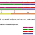
Recently, several standards have emerged that are important to connected factories, as shown below:
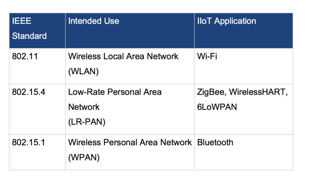
IEEE 802.15.4-based networks are ideal for IIoT applications as they suit small data packets and the relatively slow packet rates of IIoT sensors. Traditional WLAN (802.11) supports applications such as video streaming, which entails higher power consumption and greater complexity.
Given the flexibility needed, many IIoT devices support multiple protocols. For example, TI’s CC2630 wireless microcontroller unit (MCU) supports 6LoWPAN, ZigBee and TI’s own SimpleLink functionality.
The MCU is a cost-effective, ultra-low-power, 2.4-GHz RF device and part of the CC26xx family. It includes a 32-bit, 48 MHz, ARM Cortex-M3 processor core and an ARM Cortex-M0-based RF block. The ultra-low-power sensor controller provides connectivity to sensors and gathers data during sleep mode, which is ideal for low-power remote sensor nodes within the IIoT.
Minimizing EMC by Design
Designing for EMC performance is complex, not least because you cannot see, smell, touch or taste EMC. A top-down approach is required, starting with the infrastructure (power distribution, grounding, etc.) and finishing with the individual device circuit boards.
Minimizing EMC: Factory Level
Power distribution systems are a major contributor to EMC and are a good place to start. High-voltage systems spawn many EMC issues due to transients created by normal operation of the distribution network.
Motors and other rotating machines are generally a major source of EMC. Brushed motors are a well-known issue, but even brushless motors can generate high-speed transients due to their PWM control. Site surveys are a good way of identifying machines that need to be shielded and/or isolated.
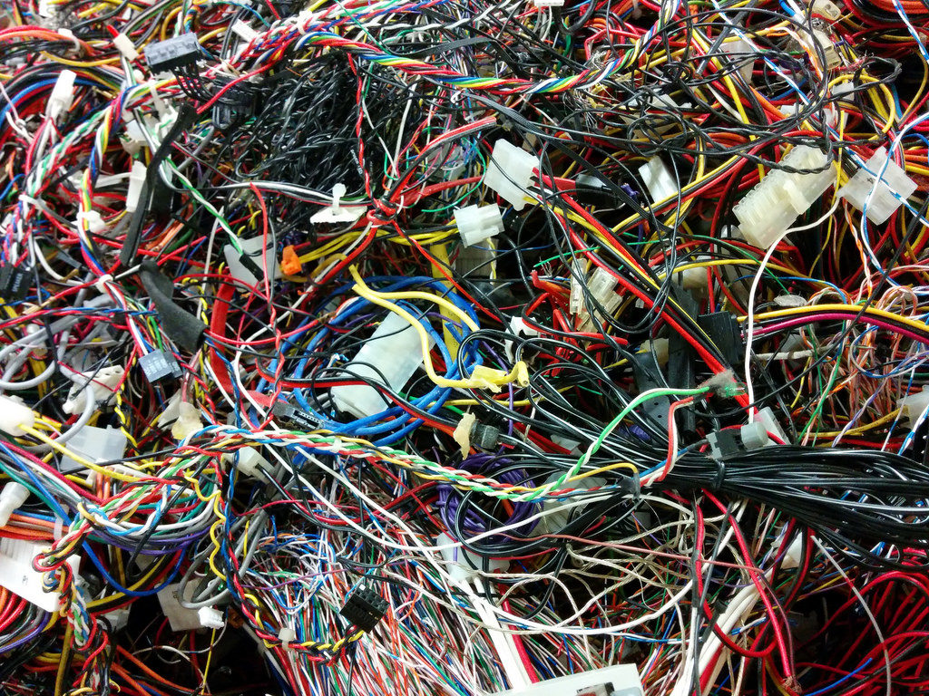
In most factories, there is a maze of wires running through walls, ceilings, floors, and conduits. As most factories have evolved with wiring being added over time, it is quite common that high-voltage/high-current cabling is mixed with sensitive high-impedance sensor and transducer cabling.
Cabling can act as an antenna, inductively picking up EMC from an adjacent cable and propagating it to sensitive devices. Shielded cabling is a very effective way of protecting signals that are sensitive to noise. Even though shielded cabling costs slightly more, it is a significant cost savings over the expense of finding and addressing EMC issues later on.
One excellent cable is Belden’s 9536, which has six 24-AWG stranded, tinned copper conductors within semi-rigid PVC along with a shield and a drain wire. Belden’s 796x cable is ideal for use in Cat5e 100BaseTX cable trays, offering an industrial-grade PVC outer layer over four conductors and a braided shield.
There is an excellent range of flexible braided tubing, conduit, and fittings to provide EMI protection from Glenair. As an example, its Armorlite is braided nickel-clad stainless-steel EMC shielding suitable for applications up to 260°C.
Minimizing EMC: System Level
IIoT node-level devices typically comprise many components that contribute to EMC issues. Conducted noise can enter via any power or signal wire, and the wireless portion can emit EMC, or be susceptible to external EMC.
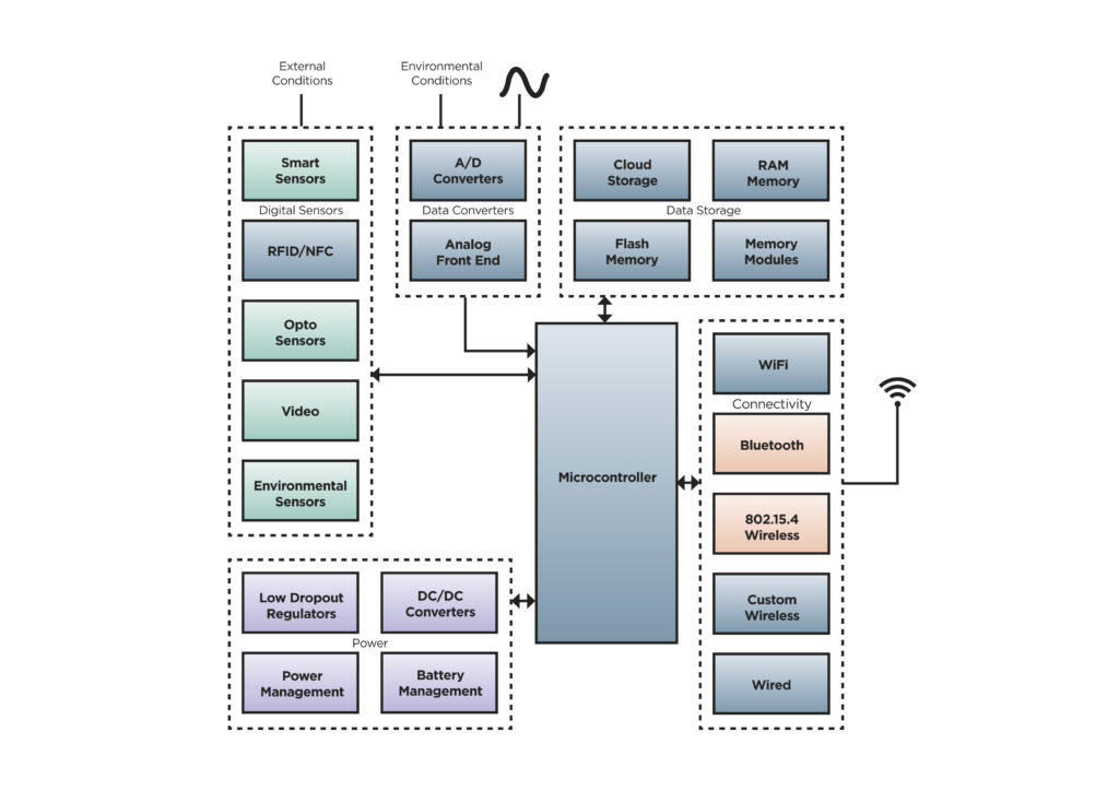
The best place to deal with conducted issues is the periphery of the device – stop the noise where it leaves or enters the device. Filtered connectors are very effective for this approach and, as the filter elements are within the connector, there is no impact on PCB space as there would be with standard connectors as discrete suppressors.
D-sub connectors from Harting include a ferrite filter to suppress high frequencies and are available in 9-, 15-, 25- and 37-contact versions.
High-voltage DC is best filtered away from the PCB. API’s 51F-726-002 EMC feed-through filters are suitable for mounting in a threaded- or through-hole. The filters incorporate resin seals, making them suitable for industrial environments where they can handle voltages up to 500 V DC/220 V AC (400 Hz). A choice of C, L or Pi filters is available.
TI’s TPDxF003 family reduces EMI emissions and provides system-level electrostatic discharge (ESD) protection by dissipating ESD strikes in excess of the needs of IEC 61000-4-2 by providing high-frequency roll-off. With a 200 MHz 3dB bandwidth, attenuation is greater than 25dB at 1GHz. Devices are available with four, six or eight channels
Although “old technology,” a simple Faraday cage can shield a sensitive device as well as stopping emissions escaping into the environment.
Minimizing EMC: Device Level
At the PCB level, radiated or conducted EM emissions can lead to problems on the same board. Modern high-speed clocks or even power supplies can interfere with high-impedance analog signal paths. It is good practice to ensure that different sections are kept separate to minimize coupling. Other useful techniques include:
- Using “star grounds” to separate high-current areas from analog sections
- Minimizing power loops and impedances by running power and ground above each other
- Adding ground planes below noisy components such as clocks or microcontrollers
There are many techniques and considerations to be taken into account, meaning that PCB design is often an iterative process.
EMC is a complex topic, and this article can only be a short overview. There are links to direct you to more resources, and some of our suppliers have their own guides including a PCB design application note from TI, a passive component-oriented EMC guide from TDK and a tutorial from Analog Devices that covers shielding of analog circuitry.




Leave a Reply
You must be logged in to post a comment.